-
Actual Calculations for Relay Protection
Use this Protection Relay Setting Calculator to calculate pickup current, time multiplier settings (TMS), operating time, coordination time interval (CTI), and plug setting multiplier (PSM) using fault current, CT ratio, and IEC 60255 curve parameters. This technical report refers to the electrical protections of all 132kV switchgear. All calculations are based on the available documentation/ information. This standard mandates that generator, transmission, and distribution owners establish a process for developing new and revised protection settings and properly coordinate their systems wi h interconnected utilities as part of Requirement 1. The protective philosophy is fundamentally grounded on the understanding that faults or abnormal operating. In HV (High Voltage) and MV (Medium Voltage) substations, relay protection safeguards critical assets such as transformers, circuit breakers, and lines.
[PDF Version]
-
Relay protection input settings
The essential parameters for relay settings include pickup voltage, dropout voltage, time delay settings, and protection thresholds. Combines protection, sensors, control power, and circuit breaker in a single package Typically added to a breaker close circuit to prevent accidental reclosure after a trip. Three fundamental components required for each circuit breaker. PSM – Plug Setting Multiplier (Current Setting Multiplier) What is PSM? 2). They are intended to quickly identify a fault and isolate it so the balance of the system. So, in this case, to protect the whole line, the setting has to be able to detect fault current above 150 A. At this setting,this is as far as we can reach down the line before the fault becomes undetectable. Power system stability means also. This handbook covers the code of practice in protection circuitry including standard lead and device numbers, mode of connections at terminal strips, colour codes in multicore cables, dos and donts in execution.
[PDF Version]
-
Techniques for Calculating Relay Protection Settings
Use this Protection Relay Setting Calculator to calculate pickup current, time multiplier settings (TMS), operating time, coordination time interval (CTI), and plug setting multiplier (PSM) using fault current, CT ratio, and IEC 60255 curve parameters. For thermal overload protection (ANSI Device 49), the pickup is typically set at 115% to 125% of motor full-load amps depending on service factor. For overcurrent. This technical report refers to the electrical protections of all 132kV switchgear. All calculations are based on the available documentation/ information. These settings may be revaluated during the commissioning, according to actual and/or measured values. Presented at the 51st Annual Minnesota Power Systems Conference Saint Paul.
-
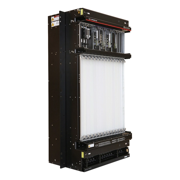
Six-Column Relay Protection Tester
Specifically designed for settings-based protection testing with a high degree of automation, our modular software Test Universe offers numerous functions and application-optimized test modules that save yo.
-
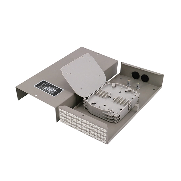
What is a reasonable installation height for fire protection distribution boxes
The proper installation of a distribution box involves placing it at the right height to ensure safety and convenience. Detectors shall be installed on the ceiling or on the wall within 300 mm (12 in. What is the standard height for a wall-mounted distribution box? What factors should you consider when choosing the installation height? What happens if the distribution box is installed too low? What tools do you need to measure the correct height? What are the risks of not following height. This image demonstrates the proper installation and height placement of various fire alarm system components as per NFPA 72. - Ensures early detection of smoke and is crucial for occupant safety. Practice good wiring: secure grounding, neat cable management, proper insulation, and correct wire gauge and breaker. What type of fire suppression you will need depends on how you use a building or premises and how it has been constructed. Based on your ideal needs, you may need to install Pyro Chem fire suppression, Ansul fire suppression, Amerex fire suppression, Buckeye fire suppression, Range Guard or Kidde. 2.
[PDF Version]
-

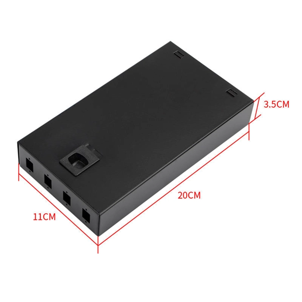
Busbar Connector Protection Box Usage
It is mainly used for insulation protection and safety protection of busbar connections in switchgear factories, power plants, and substations. In modern industrial electrical distribution systems, busbar systems serve as the backbone for power distribution, channeling electricity from main sources to various circuit protection devices and loads. The connection between molded case circuit breakers (MCCBs) and busbars represents a critical. The busbar joint protection box is made of radiation cross-linked polyolefin material. It has excellent physical, chemical and electrical properties. The high magnitude fault currents require high-speed. DEFINITIONS.
-

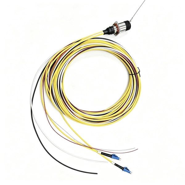
Relay Protection Test Wiring Method
One approach to test the total protection system is to use primary injection techniques (see appendix H) that trigger protective relays and lockout relay, trip circuit breakers, and initiate annunciations and indications. If applicable, documentation is required detailing how verified protection segments overlap to ensure there is not a gap. The purpose of this Standard Work Practice (SWP) is to standardise and describe the method for testing of Ergon Energy protection relays for commissioning purposes. This SWP should be interpreted in conjunction with Standard for Substation Protection (V1. From a technician's perspective, master the unique skill of testing protection. When the transformer wiring type is Y/Y (Y0), the test wiring is very simple: when testing phase A, the tester IA is connected to the phase A of the high voltage side, and the tester IB is connected to the phase a of the low voltage side. After the neutral line of the high and low voltage sides is. Function: Use electronic components like transistors to perform switching. Applications: Frequency, undervoltage, and overcurrent protection.
[PDF Version]