-
Finding Faults in Optical Time Domain Reflectometers
An OTDR sends pulses of light down a fiber optic cable and measures the reflected signals. These reflections indicate splices, bends, breaks, and other faults. What Is an OTDR? What Is an OTDR? An OTDR is. Download free OTDR Trainer Software for PCs After you study this page, you can download a free OTDR Trainer to run on your PC. It provides an expert-curated supplier directory, buyer-focused technical background information, and structured selection criteria to support professional procurement decisions. With the help of this device, engineers and technicians can accurately assess and diagnose fibers and cables. This guide seeks to clarify the perceived complexities of OTDR. An Optical Time Domain Reflectometer (OTDR) is a precision tool used to detect faults and measure loss along fiber optic links by analyzing backscattered light from high-speed pulses.
[PDF Version]
-

Price of the Burundi Dynamic Brillouin Optical Time Domain Reflectometer
A Brillouin Optical Time Domain Reflectometer can cost anywhere from $50,000 to $200,000, depending on the specifications and features. In contrast to simple optical loss test sets (OLTS) which measure only the total. The Naval Undersea Warfare Center Division, Newport (NUWCDIVNPT) is seeking a firm fixed price purchase order for one Brillouin Optical Time Domain Reflectometer (BOTDR), one travel case, and one 19" rack mount kit. The BOTDR should have the capability to measure strain and temperature in various. Guangdong Bailing Optoelectronics Technology Co. These are some of the reflections using a comparative TDR. Installers regularly. The OZ Optics' ForeSight™ family of fiber optic Brillouin distributed strain and temperature sensors (DSTS) utilizes Brillouin scattering to provide sophisticated optical sensor systems for distributed sensing.
[PDF Version]
-
Optical Time Domain Reflectometer in Democratic Republic of Congo
An optical time-domain reflectometer (OTDR) is an instrument used to characterize an. It is the optical equivalent of an electronic which measures the of the or under test. An OTDR injects a series of optical pulses into the fiber under test and extracts, from the same end of the fiber, that is scattered () or reflected ba.
-
Optical cable OTDR curve test graph
This data represents information resulting from a test of fiber optic cable using an OTDR instrument, including distance, reflectance, loss, and fiber attenuation. You can view the data from up to four. Download free OTDR Trainer Software for PCs After you study this page, you can download a free OTDR Trainer to run on your PC. The Optical Time Domain Reflectometer (OTDR) is useful for testing the integrity of fiber optic cables. It can verify splice loss, measure length and find faults. To minimize testing time, compromises must be made on accuracy (detecting low loss. An OTDR allows you to locate splices, faults and breaks in optical fiber by analyzing backscattered light. Lets take the example below: This link has pretty much every type of event you nay expect to see.
-
Multimode optical cable test length requirements
The cable should be longer than either of the following specifications, Event Dead Zone or Loss Dead Zone and the pulse length being used. Corning recommends that all fiber optic systems be tested to a minimum set of standards. So, you drop everything and i vestigate. He's right – it is n t working. Link testing of multimode segments should be done with an 850/1300nm dual wavelength unit. Since there is not an IEC/EIA. The length of launch cable used can very depending on the measurement needs. NEIS® are intended to be referenced in contrac documents for electrical construction ation or liability to users of this publication. Existence of a standard shall not preclude any member or nonmember of NECA or FOA from specifying or using. Other than for short-reach single-mode applications that are more susceptible to reflections and take connector reflectance into consideration, insertion loss testing, length, and polarity are really all you need for Tier 1 certification testing. Measured in decibels (dB), insertion loss is the. ANSI/TIA‑568.
[PDF Version]
-
How does the optical module test group perform its tests
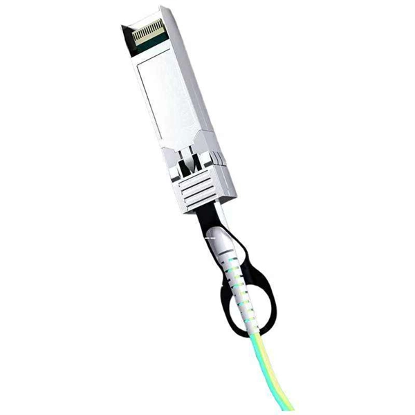
Optical modules will go through strict testing and quality inspection procedures before shipment, such as material testing, parameter testing, aging testing, real machine testing, end-face testing, etc. In fiber optic networks, optical transceivers such as SFP, SFP+, QSFP28, and QSFP-DD play a vital role in converting electrical signals into optical signals and vice versa. Testing these modules ensures performance, compatibility, and long-term reliability in bandwidth-intensive environments like. QSFPTEK suppliers have strict transceiver testing and quality control processes, and each optical module is delivered with a complete testing process. Optical modules can realize end-to-end signal transmission, and it performs optical communication through optical fibers. However, due to the architectural differences between 4-channel and.
[PDF Version]
-

Optical module test power not adjusted too low
What does it mean if the transmitted power is too low? Low transmitted power can mean the connectors are dirty. Clean the connectors, check the module, and look at the fiber. If it still does not. Stable optical power is the foundation of every high-capacity optical transport system. Even minor deviations—whether too high, too low, or unstable—can impact signal integrity, trigger service alarms, or interrupt traffic on DWDM, OTN, or long-haul optical line systems. Because optical networks. The article Digital Diagnostic Function (DDM) For Optical Modules describes that DDM function can be used for real-time monitoring and fault location of the module's working status, in which the optical module's transmitting optical power and receiving optical power are the key parameters for. To test transmitted power in sfp optical modules, you use an optical power meter to get exact results. Many sfp modules also have DOM/DDM, which lets you see digital diagnostic monitoring data on network equipment. Built into modern SFP/SFP+/ SFP28 /QSFP family modules and standardized by SFF-8472, DDM/DOM exposes real-time values for the module's temperature, supply.
[PDF Version]
-
Malaysia Delivery Time for 40G Optical Receiver
Delivery time for East Malaysia (8-10 Business days) as the location of the stock hub is in Penang. Our delivery. What Does the status means? What Does the status means? Track your parcel's journey from start to finish with GDEX's easy-to-use parcel tracking service. Track shipping to be in control every step of the way. Please ask for the stock availability first to avoid any disappointment. Specifications Features 40G QSFP+ Optical Stack Cable (included both side transceivers), 5. The DSC-R401HG is a linear and versatile PIN + transimpedance amplifier suited for a variety of digital and analog applications. The R401HG offers a linear response to > +3 dBm optical input, 600mVp-p of linear output voltage, 20 GHz of RF bandwidth and a conversion gain of 160 V/W.
-

Benin Optical Cable Blowing Machine
A cable blowing machine (also known as a fiber blowing machine) is a machine designed to fit cables into telecommunication ducts and with the use of compressed air or water.
-
The function of a 10 Gigabit optical splitter
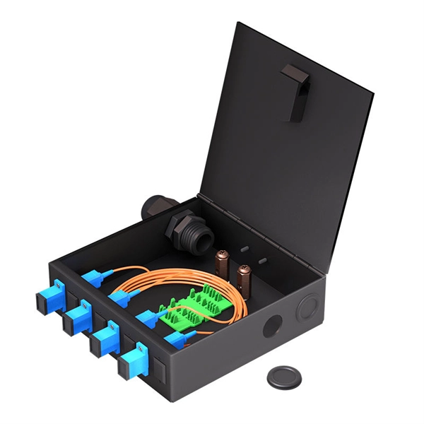
By dividing a single optical signal from a central Optical Line Terminal (OLT) into multiple outputs for Optical Network Terminals (ONTs) at users' homes, splitters eliminate the need for dedicated fibers to each residence—slashing infrastructure costs while scaling network reach. An Optical Splitter, also known as a beam splitter, is a passive optical device that divides a single input optical signal into two or more output signals. Conversely, it can also combine multiple signals into one. Optical splitter. Where splitters are placed in the network can make significant impacts on fiber counts, network cost and deployment time and operational steps, such as customer onboarding and maintenance. One important note is that splitting architectures should be seen as tools that can be mixed and matched to. The trick is how that single signal gets divided. That's where splitters come in.
[PDF Version]
-
Switches are all 10 Gigabit optical
To implement different 10GbE physical layer standards, many interfaces consist of a standard socket into which different physical (PHY) layer modules may be plugged. PHY modules are not specified in an official standards body but by (MSAs) that can be negotiated more quickly. Relevant MSAs for 10GbE include (and related X2 and XPAK), and. When choosing a PHY.