-
MEMS optical switch design
In figure 1.2 a row of protection switches is shown that is used in parallel optical connections (e.g. bus connections between computers). All channels have to be switched at the same time to reroute the signals from one computer to ano. In figure 1.2 a row of protection switches is shown that is used in parallel optical connections (e.g. bus connections between computers). All channels have to be switched at the same time to reroute the signals from one computer to another. Protection switching is required to avoid a permanent interrupt of a connection due to fiber break or due to. mirror / shutter surface micromachining Si-On-InsulatorElectromagnetic actuators are used in optical switches, as these actuators are known from precision machined solutions and the actuating part is a simple coil of many turns of wire. The ferromagnetic materials required in microsystems can easily be realized by sput-tering or electroplating of Permalloy. Additionally, the combination of permanent ma.
[PDF Version]
-

Principles and Product Design of Optical Fiber Communication
Optical Fiber Communication (OFC) revolutionizes modern telecommunications, enabling rapid data transfer across long distances with minimal signal loss. This comprehensive review explores OFC's historical evolution, core principles, components, and versatile applications. Kanade Department of Electronic-Science, P. College of ASC, Pravaranagar, India fPublished. The digital communication techniques discussed so far have led to the advancement in the study of both Optical and Satellite communications. Light acts as a carrier wave and can be modulated to carry information. Higher bandwidth (extremely high data transfer rate).
-
Optical Module Base Design
Optical module usually consists of a transmitter assembly (TOSA, containing a laser LD chip), a receiver assembly (ROSA, containing a photodetector PD chip), a driver circuit, an optoelectronic interface, a heat sink (some models), a housing, a pull ring and so on. Integrated circuits and reference designs help you create a smaller and faster optical module design used in high-bandwidth data communication applications. Whether you are creating a 100-Gbps or 400-Gbps, small form-factor pluggable (SFP) module, SFP+ transceiver, XFP module, CFP, X2/XENPAK module. Designing and producing these complex PCBs presents formidable challenges, requiring a convergence of disciplines—from high-frequency signal integrity and advanced thermal management to micron-level mechanical precision. These three laser diodes are described in more detail. contact us product page Copyright © 2024 MVSLINK. Critical Metrics: Signal integrity (insertion loss, return loss) and thermal management are the two.
[PDF Version]
-

Determining if an Optical Coupler is Good or Bad
Testing an optocoupler IC with a multimeter involves a two-step process: first, verifying the functionality of the LED using the diode test mode, and second, checking the phototransistor's response to light by measuring its resistance in both light and dark conditions. A forward voltage drop within the expected range indicates a functioning LED. A reading near 0 volts in either direction suggests a. Insertion loss is a critical parameter that determines the signal loss incurred when light passes through a coupler or adapter. Planar Lightwave Circuit (PLC) Couplers: PLC couplers utilize semiconductor. There are many different applications for optocoupler circuits, so there are many different design requirements, but a basic design for an optocoupler providing isolation for example between two circuits, simply involves the choice of appropriate resistor values for the two resistors R1 and R2.
[PDF Version]
-
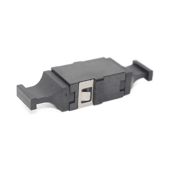
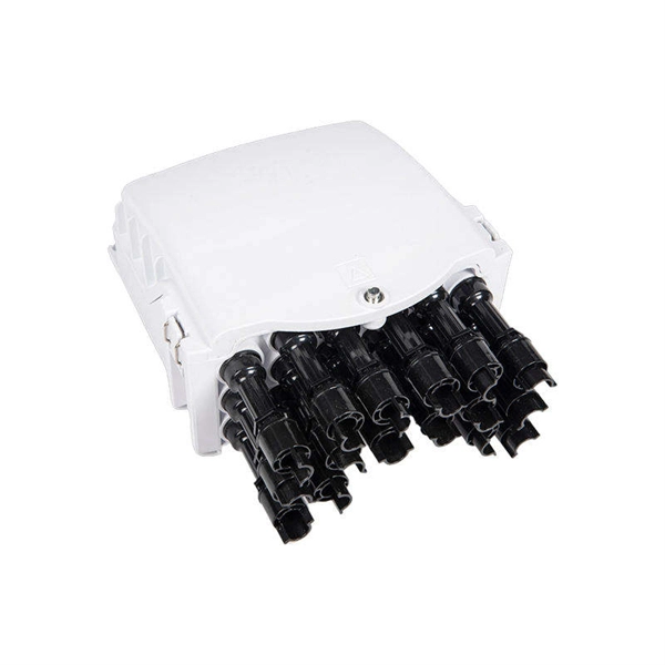
Coupler connection to optical fiber
Fiber optic couplers can either be passive or active devices. Passivefiber optic couplers are said to be passive as no power is required for operation. They are simple fiber optic components that are used to redirect light waves. Passive c. Fiber optic couplers can either be passive or active devices. Passivefiber optic couplers are said to be passive as no power is required for operation. They are simple fiber optic components that are used to redirect light waves. Passive couplers either use micro-lenses, graded-refractive-index (GRIN) rods and beam splitters, optical mixers, or spl. Types of fiber optic couplers include splitters, combiners, X-couplers, trees, and stars, which all include single window, dual window, or wideband transmissions. Fiber optic splitterstake an optical signal and supply two outputs. They can further be described as either Y-couplers or T-couplers. 1. Y-couplershave equal power distribution, meaning t. When specifying optical couplers you should consider the fiber optic cable, the coupler type, signal wavelength, number of inputs and outputs, as well as insertion loss, splitting ratio, and polarization dependent loss (PDL).
[PDF Version]
-
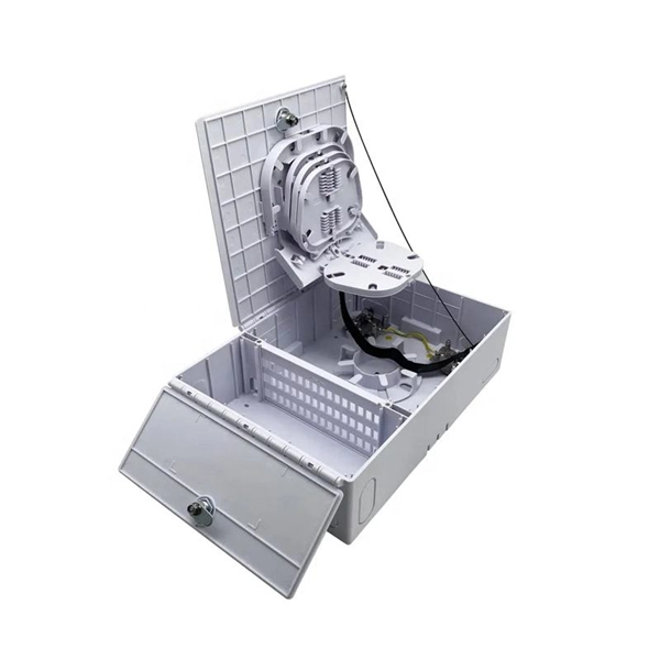
Optical Ground of Fiber Optic Communication Line
OPGW (Optical Ground Wire) is a kind of cable that comprises the dual functions of grounding and fiber optic communication. It is increasingly utilized in high-voltage transmission lines as a functional element that both safeguards the power system and allows data sharing across the. An optical ground wire (also known as an OPGW or, in the IEEE standard, an optical fiber composite overhead ground wire) is a type of cable that is used in overhead power lines. Widely used in overhead transmission lines, OPGW plays a crucial role in modern smart grids, telecom integration, and utility infrastructure.
-
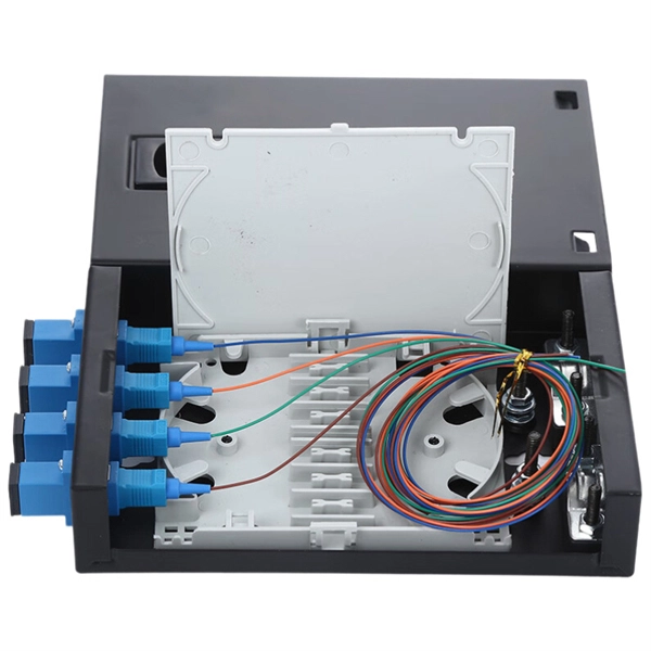
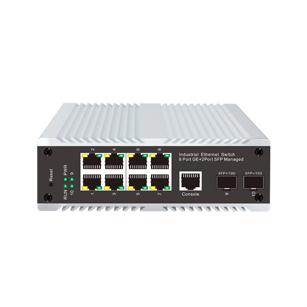
North Macedonia Optical Line Terminal 10G
The 10G SFP+ LR Ethernet Line optical transceiver transmits data over single mode fibre at a distance of up to 10km. The transceiver operates on 1 wavelength and works in point-to-point scenario. Modern OLTs offer communication service providers (CSP) the ability to launch multigigabit services to tens of thousands of subscribers from a single location or just ten. Fiber-to-the-home. HA7308VX is a small capacity 8 port OLT device launched by HiOSO. It can be used with HA7200 series ONU and passive optical distribution network (ODN) to form a passive optical network to achieve performance management, fault management, and configuration management of the equipment. 5G/5G/10GBase-T Multi-rate SFP+ Module (Twisted Pair Category Cable, 100m 1G/2. 5G Cat5e, 70m 5G Cat5e, 30m 10G Cat6a/7, RJ-45, C-temp) Specifications Form. Field-proven EPON and 10G-EPON OLT SoC solutions Cortina family of Optical Line Terminal (OLT) SoCs completes the end-to-end solutions for EPON and 10G-EPON applications.
[PDF Version]
-
Hazards of Laying Optical Cables
Optical fibers, though renowned for their efficiency and bandwidth, aren't immune to risk factors that could spawn safety hazards. The very nature of fiber optic cabling requires handling microscopic strands that, when damaged, can cause signal loss or, worse, physical harm. Understanding the safety hazards that go with fiber optic cable is critical for those who install or maintain fiber optic systems. As electrical professionals, most of us take fiber optic (FO) safety for granted. Recognizing the potential safety hazard inherent in the installation and maintenance of optical fibers is crucial to mitigating risks of personal or property damage. Know the standards that apply to your work Whether you're installing new fiber optic cables or troubleshooting and repairing an existing fiber network, a working knowledge of the regulations that apply to your. However, fiber optics installation is not without risks. Even the output of OTDRs, WDM and fiber amplifier systems, which are. Working with fiber optic cabling requires precision, skill, and a strong understanding of cabling safety.
[PDF Version]
-
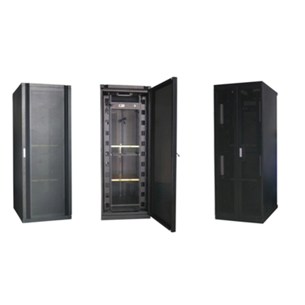
Protection Measures for Optical Cable Line Engineering
Optical cable lines lightning protection and strong current protection are achieved by avoiding, guiding or discharging them underground to prevent lightning and strong current from causing damage to the optical cable lines themselves, communication equipment and personnel. Since the lightning. The Fiber Optic Association, Inc. The conduit can be made of various materials such as PVC, HDPE, or steel. It is suitable for areas with flat terrain and small undulations. This type of fiber optic is laid in two ways: suspended under steel strand and self-supporting suspension. Local exchange carriers use fibres to carry the same service between central office switches at local levels, and sometimes as far as the neighbourhood or individual home.
-
Direct Sales of Gigabit Optical Modules from Manufacturers in Mali
U.S. exporters should identify a local agent or distributor to assist in bringing goods to market in Mali. Businesses should be aware, however, that entering a successful partnership or representational relatio.