 Guide
Guide Demystifying the Fiber Optic Coupler: The Unsung Hero of Light
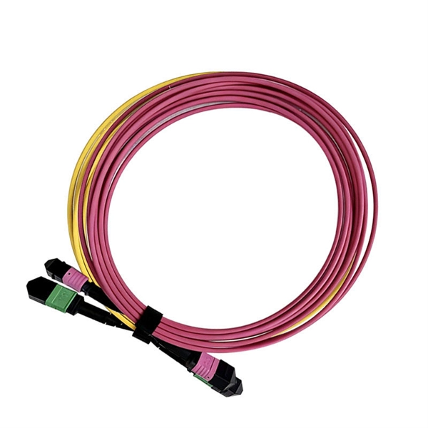
A fiber optic coupler splits or combines light signals in optical networks, improving data flow, reliability, and network flexibility for various applications.
 Guide
Guide Testing Methods for Optocouplers | PDF
The document describes 3 methods for testing opto-couplers to determine if they are functioning properly or bad. The methods involve using a multimeter to measure
 Guide
Guide What is an Optocoupler and How to Choose the Right One?
When comparing different optocoupler types, factors such as response time, CTR, and isolation voltage should be considered. By understanding the characteristics of each type, you can make an informed
 Guide
Guide Using Opto Couplers
In choosing appropriate values for R1, the value for the current limiting resistor is set to produce the correct forward current (I F) through the infrared LED in the optocoupler. R2 is the load resistor for
 Guide
Guide How To Check Optocoupler Ic With Multimeter? A Simple Guide
Before testing the entire optocoupler, it''s crucial to check the LED''s functionality. Set your multimeter to the diode test mode. This mode typically injects a small current into the diode and
 Guide
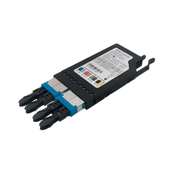
Guide How to test the quality of the coupler and optical fiber adapter
Testing the quality of couplers and optical fiber adapters is crucial to ensure reliable and efficient connections in fiber optic networks. Here are some methods commonly used to test the
 Guide
Guide How to Choose the Right Fiber Coupler (FTTH, Data Center & More)
This information will give network designers and technicians the ability and confidence to select a fiber optic coupler that maximizes performance and plans for the future of optical networks.
 Guide
Guide How to Choose the Right Fiber Coupler (FTTH, Data
This information will give network designers and technicians the ability and confidence to select a fiber optic coupler that maximizes performance
 Guide
Guide Optical Couplers | Efficient, Versatile & Reliable
Explore the fundamentals of optical couplers, their types, mechanics, and diverse applications in telecommunications and beyond for efficient signal processing.
 Guide
Guide Testing Fiber Optic Couplers, Splitters Or Other Passive Devices
Mode Conditioning can be very important to testing couplers. Some of the ways they are manufactured make them very sensitive to mode conditioning, especially multimode but even some types of
 Guide
Guide HOW TO TEST OPTOCOUPLER ICs CHIPS test integrated circuit
Good LED present voltage drop across when applying forward bias. Picture number 2 is reverse biasing to LED so we will see " OL " ( Over Limt) display mean LED is still good.
 Guide
Guide Optical Coupler
A widely used approach for optical couplers fabrication is based on the coupling between optical fibers. The operation principle of the light coupler employed on the compensation technique is shown in Fig.
 Guide
Guide A Review of Optical Coupler Theory, Techniques, and Applications
Coupling at optical frequencies presents challenges to achieving high efficiency, compactness, high fabrication tolerance, and ease of integration in photonic integrated circuits. The paper...