-
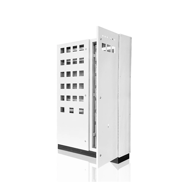
How many beam splitters can be placed in a FTTH
Traditional GPON networks often employ 1:32 or 1:64 splits, while XGS-PON allows higher ratios such as 1:128. However, higher splits reduce the power margin and limit reach, so engineers must carefully calculate the optical budget. These signals are divided by optical splitters and delivered to Optical Network Terminals (ONTs) at the customer premises. A key challenge is determining how many users a single OLT port can support, which is defined by the split ratio. PLC splitters: higher precision, good for large ratios (e. The Passive Optical Network (PON) splitting may. Optical splitters play an instrumental role in the Passive Optical Network (PON), enabling a single PON interface to be shared amongst multiple subscribers. Splitters can be placed everywhere. Output cables will connect to 32 families ONT through patch panel, splicing conjunction. Therefore, PON connects one OLT port.
[PDF Version]
-
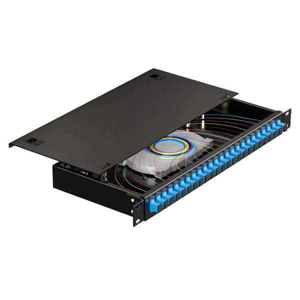
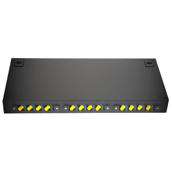
Optical splitters are divided into box-type and
Optical splitters can be divided into two types based on their working principles: Planar Lightwave Circuit (PLC) optical splitters and Fused Biconic Tapered (FBT) optical splitters. Optical splitters are a very important component in fiber optic links, widely used in. A fiber optic splitter is a passive optical component that divides a single incoming optical signal into two or more outgoing signals, or combines multiple incoming signals into one.
-

How to route fiber optic cables for high-voltage power lines
This technique takes a small, lightweight fiber optic cable and wraps it around or lashes it to the power line. The cable is called optical power attached cable (OPAC), and it is lashed to the power cable with a specialized tool that is pulled from the ground, such as a. Installing ADSS (All-Dielectric Self-Supporting) cables near live power lines demands precision, compliance with safety standards, and an understanding of high-voltage risks. This guide from GL FIBER breaks down the process into actionable steps, aligned with IEEE 524 and IEC 61935-1 protocols, to. Most aerial fiber optic cables are installed by lashing to a steel messenger wire strung between poles, but there is a category of cables with special high-strength jacket designs called all-dielectric self-supporting (ADSS) cables. ADSS cables are designed to withstand very high-tension loads. bles in a high voltage environment, with typical line voltages of 115 kV or more, requires the evaluation of certain critical parameters. Curr ntly, there are a limited number of industry documents that address the requirements for optical fiber cables near high voltage circuits.
[PDF Version]
-
How to connect a 2-to-8 splitter
Attach the short length of the coax cable to the wall outlet and to the IN port of the splitter. Dive into the world of cable management with our comprehensive educational video. But now the query is; How to use a cable. However, connecting one splitter to another—also known as cascading splitters—can be tricky. In this guide, we'll explain how to safely connect a splitter to another splitter, covering both fiber. Installing a 2-way coaxial splitter is a simple yet crucial step when it comes to setting up a home entertainment system or establishing a cable TV network.
-
How to deal with abnormal noises from fiber optic terminal boxes
From SPL meters to spectrum analyzers, technology provides the means to uncover these invisible nuisances. Once identified, simple yet effective measures like relocation, soundproofing, and firmware updates can mitigate their impact. A fiber termination box is the standard instrument used in fiber optic networks to connect, secure, and protect optical fibers at the terminating point. When issues like signal loss, slow speeds, or intermittent connectivity arise, systematic troubleshooting is key. Before. Proper troubleshooting can help quickly identify and resolve issues to minimize downtime.
-
How to bring the pigtail out of the junction box
In this step-by-step guide, we will explore the process of replacing a pigtail connector. This article will walk you through the necessary steps and provide. The instructions say to wrap the wires from my junction box around the screws on the back of the lampholder But the wires coming out of my junction box are all pigtailed, making it impossible to wrap them around the screws Take another piece of wire (called a pigtail) and twist it in with the. In this article, you'll learn how to splice a single gang junction box. A single gang electrical box (one gang box) is where electricians install a switch, plug, or thermostat! We splice wires in the box to carry on power (junction box), or use switch legs to turn a light on or off. A 'pigtail' is simply an extension that is added to a piece. The National Electrical Code (NEC) limits " box fill," aka how much you can stuff in there. Below, I'll show you how to do it, too. To remove a junction box, you typically need to turn off the power, assess its mounting.
[PDF Version]
-
How to connect fiber optic cable to switch 6
Connect the fiber optic cable: Attach the fiber optic cable's connector to the transceiver module on the switch. Make sure the connector type (e. Network topology refers to the way in which the links and nodes of a network are arranged in relation to each other. Simply put, it defines how network. In this guide, we'll walk you through how to connect a fiber optic cable to a router safely and efficiently. Advantages Determine the length of the fiber run and choose either multi mode for runs under 1000 feet or single mode for runs over 1000 feet.
-

How to connect the power supply to a fiber optic switch
We'll show you how to connect power and network using a fiber optic cable linked to the core switch in the control room. No extra adapters needed—just plug directly into an AC outlet. This setup is perfect for extending your network to outdoor IP cameras or remote locations. more Learn. Fiber connectivity to the power supply will pass through a standards-based SFP (small form-factor pluggable) interface which allows operators to communicate with the power supply using their chosen vendor solution. The opportunities and efficiencies they offer speak for themselves—but, as they spread to locations both indoors and out, you're probably feeling the crunch caused by not having enough. While in this post, we mainly focus on the PoE system that using fiber optic with power to solve unusual applications specifically in real life, which may need to achieve greater distance, higher bandwidth, or better reliability. Concerns go from laying. CONFIGURING THE SWITCH IN DESIGO CC/CERBERUS DMS.
[PDF Version]
-
Want to learn how to fuse 24-core optical fiber cables
Learn how to splice fiber optic cable using fusion splicing with this complete step-by-step guide. Includes tools, best practices, loss standards (ITU-T G. 652), cost analysis, and FAQs for network engineers and installers. In this guide, you will find a chronological description of the fusion splicing process, the principal technical standards, and answers to the real-life questions network engineers and procurement teams may have. Therefore, we will also touch on cost factors, risk management, and best practices in. With this in mind, we have prepared the ultimate guide on how to use a fusion splicer on fiber optic cables. This article provides a detailed explanation of the sequence, covering four aspects: preparation, stripping and cleaning, fusion splicing, and testing.