 Guide
Guide Everything you need to know about Fiber Optic Testing
Fiber optic sources, including test equipment, are generally too low in power to cause any eye damage, but it''s still a good idea to check connectors with a power meter before looking into it.
 Guide
Guide How to Test a Fiber Optic Cable: Best Methods & Tools
Want to know how to test a fiber optic cable? We''ll look at the most common fiber testing methods and how to use them properly.
 Guide
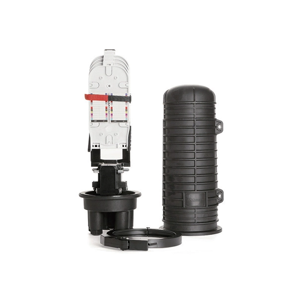
Guide Fiber Rings, OTDR, Single Mode, SC-ST Connector, 150m
It is essential for testing optical fiber links in premises networks. OTDR testing requires launch and receive test cables to measure the end-to-end loss of fiber optic links. The coiled OTDR launch cable
 Guide
Guide AFL FR1-SM-150-SC-SC
Launch and receive test cables can range from 150 m to 1 km (or longer) in length. Because very long test cables are impractical to transport and use, AFL offers coiled lengths of 50 µm multimode, 62.5
 Guide
Guide Fiber Optic Cable Testing Methods |Fluke Networks
Fiber optic testing by Fluke Networks ensures network performance and reliability. Includes signal loss, quality checks, and more.
 Guide
Guide How to Test a Fiber Optic Cable: Best Methods & Tools
The test configuration depicted in Figure 3 includes a test source on one end (which generates the light signal), and a test meter on the opposite end (which receives the light signal).
 Guide
Guide How To Test Fiber Optic Cable: Best Testing Methods Explained
Learn how to test fiber optic cable across every location and get best practices to simplify your next fiber test in this guide by TailWind.
 Guide
Guide The FOA Reference For Fiber Optics
See the Test section of the FOA Online Guide for much more detail. After fiber optic cables are installed, spliced and terminated, they must be tested. For every fiber optic cable plant, you need to test for
 Guide
Guide FOA Fiber U Quickstart Guide: Fiber Optic Testing
This is your "QuickStart" guide to testing fiber optic cable plants, patchcords and communications equipment with a fiber optic light source and power meter. We''ll give you the basic information you
 Guide
Guide How To Test Fiber Optic Cable
This article outlines essential fiber certification processes, test equipment considerations, and methodical procedures to guarantee flawless fiber connections in current and future high-speed
 Guide
Guide Fiber Optic System Testing Tutorial
The test configuration depicted in Figure 3 includes a test source on one end (which generates the light signal), and a test meter on the opposite end (which receives the light signal).