-
Actual Calculations for Relay Protection
Use this Protection Relay Setting Calculator to calculate pickup current, time multiplier settings (TMS), operating time, coordination time interval (CTI), and plug setting multiplier (PSM) using fault current, CT ratio, and IEC 60255 curve parameters. This technical report refers to the electrical protections of all 132kV switchgear. All calculations are based on the available documentation/ information. This standard mandates that generator, transmission, and distribution owners establish a process for developing new and revised protection settings and properly coordinate their systems wi h interconnected utilities as part of Requirement 1. The protective philosophy is fundamentally grounded on the understanding that faults or abnormal operating. In HV (High Voltage) and MV (Medium Voltage) substations, relay protection safeguards critical assets such as transformers, circuit breakers, and lines.
[PDF Version]
-

Techniques for Calculating Relay Protection Settings
Use this Protection Relay Setting Calculator to calculate pickup current, time multiplier settings (TMS), operating time, coordination time interval (CTI), and plug setting multiplier (PSM) using fault current, CT ratio, and IEC 60255 curve parameters. For thermal overload protection (ANSI Device 49), the pickup is typically set at 115% to 125% of motor full-load amps depending on service factor. For overcurrent. This technical report refers to the electrical protections of all 132kV switchgear. All calculations are based on the available documentation/ information. These settings may be revaluated during the commissioning, according to actual and/or measured values. Presented at the 51st Annual Minnesota Power Systems Conference Saint Paul.
-
Relay protection input settings
The essential parameters for relay settings include pickup voltage, dropout voltage, time delay settings, and protection thresholds. Combines protection, sensors, control power, and circuit breaker in a single package Typically added to a breaker close circuit to prevent accidental reclosure after a trip. Three fundamental components required for each circuit breaker. PSM – Plug Setting Multiplier (Current Setting Multiplier) What is PSM? 2). They are intended to quickly identify a fault and isolate it so the balance of the system. So, in this case, to protect the whole line, the setting has to be able to detect fault current above 150 A. At this setting,this is as far as we can reach down the line before the fault becomes undetectable. Power system stability means also. This handbook covers the code of practice in protection circuitry including standard lead and device numbers, mode of connections at terminal strips, colour codes in multicore cables, dos and donts in execution.
[PDF Version]
-
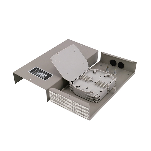
Protection level of busbar connectors
The International Electrotechnical Commission (IEC) sets out standardized testing procedures and benchmarks to ensure that busbar contact resistance remains within safe and acceptable limits. IEC standards are developed through international consensus and are used globally. The integrity of busbar joints is critical because. Busbars in power systems are the location where transmission lines, generation sources, and distribution loads converge. Because of this convergence, short circuits located on or near the busbar tend to have very high magnitude currents. The high magnitude fault currents require high-speed. Industry data shows that loose or improperly torqued busbar connections account for a significant percentage of electrical panel failures. Busbar distribution ensures these requirements are fully met. Performance criteria of. DEFINITIONS.
[PDF Version]
-

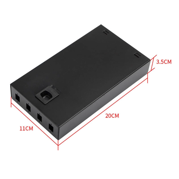
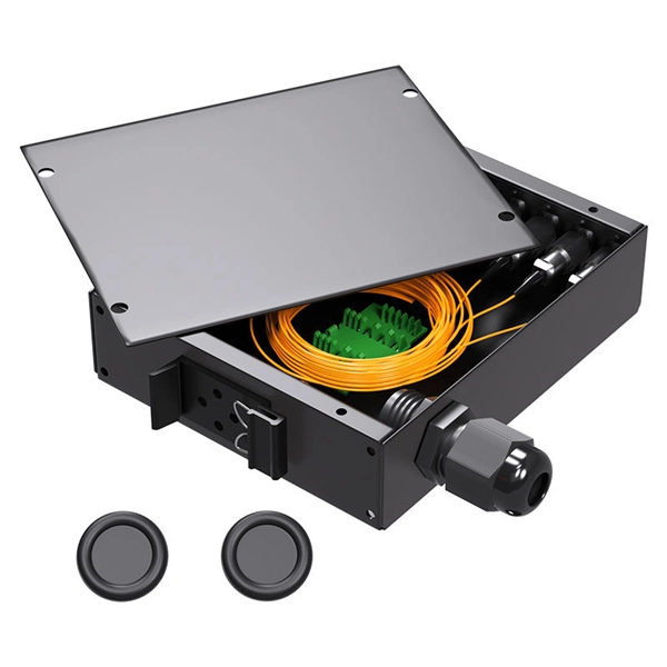
Busbar Connector Protection Box Usage
It is mainly used for insulation protection and safety protection of busbar connections in switchgear factories, power plants, and substations. In modern industrial electrical distribution systems, busbar systems serve as the backbone for power distribution, channeling electricity from main sources to various circuit protection devices and loads. The connection between molded case circuit breakers (MCCBs) and busbars represents a critical. The busbar joint protection box is made of radiation cross-linked polyolefin material. It has excellent physical, chemical and electrical properties. The high magnitude fault currents require high-speed. DEFINITIONS.
-
Wired Channel for Relay Protection
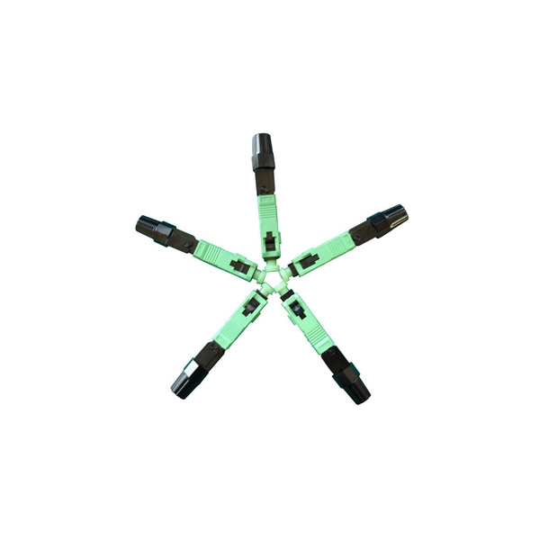
With the addition of a line tuner, the CCVT (used for potential input to the protective relay) can be used to couple the PLC signal to the power line. Protection systems are used to isolate faulted parts of the system, protect the electric system from instability, and minimize equipment damage. Directional distance and overcurrent schemes, interfaced with communication equipment, send and receive logic-based information between relay te minals to determine if the fault is external or internal to the. Important benefits include limiting tripping to faulted line section, high-speed simultaneous clearing for all internal line faults, preventing overtripping on external faults, and reducing transmission line and station damage. Applications of the concepts to accepted transmission line-protection schemes are also presented.
-

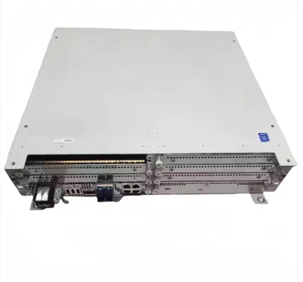
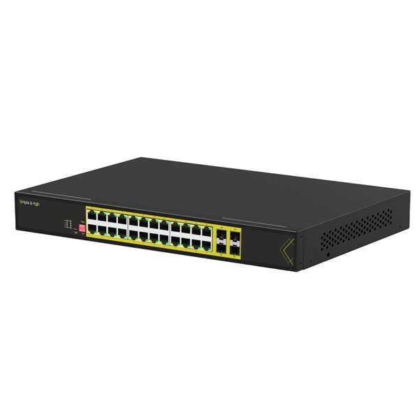
Circuit Breaker Relay Protection Equipment Model
Microprocessor-based solid-state digital protection relays now emulate the original devices, as well as providing types of protection and supervision impractical with electromechanical relays.OverviewIn, a protective relay is a device designed to trip a when a is detected. The first protective relays were electromagnetic devices, relying on coils operating on moving par. Electromechanical protective relays operate by either, or. Unlike switching type electromechanical with fixed and usually ill-defined operating voltage thresholds. Electromechanical relays can be classified into several different types as follows: "Armature"-type relays have a pivoted lever supported on a hinge or knife-edge pivot, which carries a moving contact. These relays may.
-
Several characteristics of relay protection are
To provide effective and reliable protection to the power system, a protective relay must have the following essential functional characteristics: Selective, Fast, Stable, Reliability, Sensitivity, Simple Construction and Installation Mechanism, and Cost-effective. A protective relay is an electrical switch which can automatically operate when a fault or any other abnormal conditions occur in the electrical system. It sends a signal to turn on the alarm or indicator or trip a circuit breaker to separate the faulty part from the healthy section. : 4 The first protective relays were electromagnetic devices, relying on coils operating on moving parts to provide detection of abnormal operating conditions such as. A protective relay is an intelligent electrical device designed to detect faults in power systems and initiate corrective actions such as tripping a circuit breaker. PSM – Plug Setting Multiplier (Current Setting Multiplier) What is PSM? 2).
[PDF Version]
-
Factors affecting relay protection
Other Factors: Springs losing resiliency, poor contact alignment, open coils, improper ratings, and physical damage can also break a relay. Proper selection, usage, and maintenance can help prevent these issues. One of the most common causes of relay failure is overloading and. Previous experience in designing low voltage and medium voltage switchgear, relay panels and custom control panels as an Electrical Engineer at ESSMetron, Denver CO. Graduated with a Master of Science in Electrical Engineering from The University of Texas at Dallas in 2018 and with a Bachelor of. The selected protection principle affects the operating speed of the protection, which has a significant im-pact on the harm caused by short circuits. The calculation of relaying load limits for use in comparing to transmission line load limits or other limits is discussed. This document provides recommendations, background and philosophy on relay protection that is not available in M07. This text aims to provide an.
[PDF Version]