-
Optical modules are used in switches
Switch optical modules, which convert electrical signals to optical signals and vice – versa, and optical interfaces, which serve as the physical connection points, play a pivotal role in determining the speed, distance, and reliability of data transmission. Everything you need to build an optical network from end-to-end. Common optical module types such as SFP. SFP (Small Form-factor Pluggable) is a compact, hot-pluggable network interface module used to connect network devices (switches, routers, firewalls) to fiber optic or copper cables. Think of it as the “translator” for your network equipment, converting electrical signals into optical signals. Describes what an optical module is and FAQs, including the fundamentals, appearance and structure, key performance counters, common types, and naming conventions of optical modules, causes of optical module failures and corresponding protection measures, types of optical modules supported by. An optical transceiver module, often simply called an optical module, acts as a signal conversion interface in fiber optic networks.
[PDF Version]
-
Optical switches are cheaper than electrical switches
Optical: Optical switches can have a higher initial cost due to the technology involved. They're a core component in fiber-optic networks, where data travels as pulses of light through glass fibers. Every time that light needs to change direction or jump. Optical switching represents a fundamental technological evolution, shifting data routing from the domain of electrons to the realm of photons, or light. This transition allows data to remain in its native optical form as it travels through fiber optic networks, eliminating the need for. Dater centers (DCs), consisting of tens thousands of servers connected by large switching networks, provide the infrastructure for online applications and services such as cloud computing, social networks, file storage, and web search. So, what is the difference between optical transceivers and switches? What is the Difference Between Optical Transceivers and Switches? Optical transceiver is a very cost.
[PDF Version]
-
Switches are all 10 Gigabit optical
To implement different 10GbE physical layer standards, many interfaces consist of a standard socket into which different physical (PHY) layer modules may be plugged. PHY modules are not specified in an official standards body but by (MSAs) that can be negotiated more quickly. Relevant MSAs for 10GbE include (and related X2 and XPAK), and. When choosing a PHY.
-
Optical module receiving sensitivity is less than
Receive sensitivity defines the minimum optical power required to maintain an acceptable bit error rate (BER ≤ 1E-12) at specific data rates. It's a core parameter in optical transceiver specifications, indicating the module's capability to detect weak incoming signals. What Is BER? The bit error rate (BER) measures the data transmission precision within. In optical communication systems, sensitivity is a measure of how weak an input signal can get before the bit-error ratio (BER) exceeds some specified number. For example, SONET specifies that the BER must be 10 -10 or better. This level must fall within the receiver's power range.
-
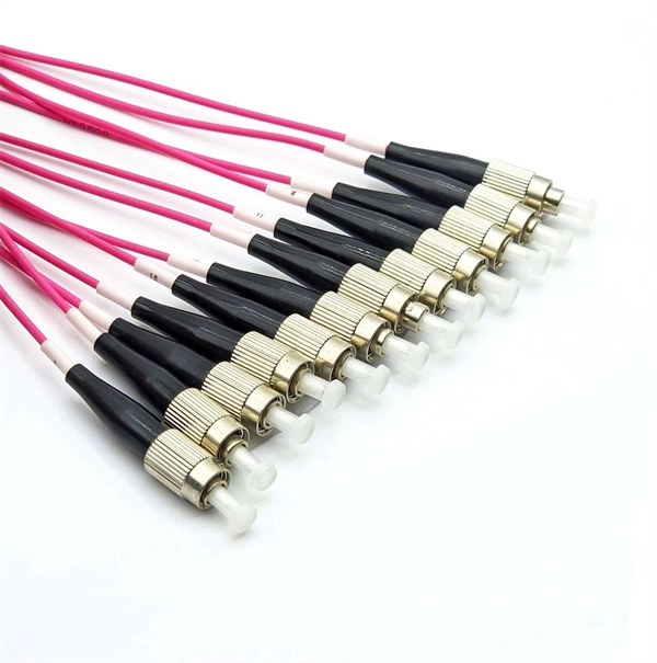
How are 36 cores of power optical fiber cable divided
Multi-core optical fiber is a breakthrough in optical networking that packs multiple cores into one fiber, enabling tremendous capacity gains via spatial division multiplexing. By carrying parallel channels in a single strand, MCF allows operators to multiply bandwidth without. These optical signals are transmitted (Tx) and received (Rx) at deliberate power levels expressed and measured in milliwatts (mW), an absolute optical power level. Absolute levels may also be represented as a relative optical power level, known decibel milliwatt or dBm. Its primary function is to split the optical signal of one input optical fiber into multiple optical signals and transmit them to. MTP/MPO cables are a class of high-density multi-core fiber optic connectivity solutions widely used in data centers and telecom networks, which are designed to achieve fast connection of multi-core fiber optics through a single interface. In contrast to conventional single-core fibers (one core on the fiber axis), MCF can have two or more.
[PDF Version]
-
How to convert an electrical port to an optical port on a switch
A switch SFP port converts electrical signals into optical signals via SFP transceivers, or maintains them electrically for copper connections. By using an SFP to RJ45 adapter (e. 5G SFP), you can seamlessly connect legacy Ethernet devices to modern fiber-optic. The RJ45 port is a built-in electrical port of a Gigabit Ethernet switch, and it is mainly connected by Category 5, Category 5e, Category 6, and Category 6e twisted-pair cables. However, modern networks often combine both technologies. The good news: you can bridge them easily using the right hardware, such as media. An SFP port on a switch or router SFP port enables network engineers to connect multiple media types, from fiber optic links to copper Ethernet. An SFP transceiver acts as a compact, hot-swappable optical transceiver that.
-

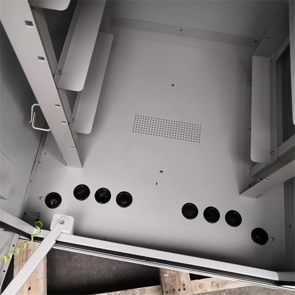
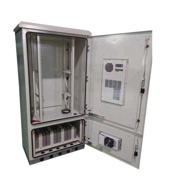
Is the H3C switch an optical port or an electrical port
H3C S1850V2-X switch series comes with standard Gigabit copper ports and Ten-Gigabit optical ports, making it a good fit for complex network environments and network expansion. H3C FS6300V2-EI series switches are a new generation of high-performance, high-port density, high-security Layer 3 Ethernet switches developed by H3C Technology Co. (hereinafter referred to as H3C) using industry-leading ASIC technology, supporting IPv4/IPV6 Dual-stack management and. A Combo port can operate as either an optical port or an electrical port. Inside the device there is only one forwarding interface. You can specify a Combo port to operate as an electrical port or an. This video provides a comprehensive guide on configuring and troubleshooting Combo ports on H3C Ethernet switches. Reasonable cable routing can improve efficiency by facilitating installation and removal of fan trays, and some other components. Interface cables are routed through the. Packaging Details:1. Rated voltage range: -48 ~ -60V DC.
[PDF Version]
-
List of Materials for Outdoor Optical Cable Cabling
Each optical cable is constructed using a precise combination of optical fibers, strength members, buffer tubes, water-blocking elements, armoring, and protective jackets. Here is the extended technical table of all raw materials used in the fiber optic cable industry. Fiber optic cables for outdoor applications are engineered to withstand the more demanding conditions seen outside, from environmental extremes to mechanical forces. These are the outdoor fiber optic cables you see strung along telephone poles (aerial), installed inside an underground duct, or even. Fiber optic cables are designed to provide high-speed, no-signal-loss, and EMI-free communication in telecommunication, powergrid, datacenter, broadband, and industrial applications. As the backbone of modern telecom infrastructure, these cables come in specialized designs to operate reliably despite the challenges of humidity, tension, wind, rodents. This document serves as a guide for outdoor fiber optic cable selection and installation for professionals in the telecommunications industry.
[PDF Version]
-
Laying optical cables on the road
The document outlines steps like obtaining permissions, excavating trenches, laying ducts, providing additional protection, backfilling trenches, and performing optical tests after installation. This article gives an overview of this technology, which enables road-surface wiring by installing optical-fiber cables in grooves formed on asphalt pavement. Light signals traveling through a pure glass core offer significantly greater bandwidth and signal integrity, making it the preferred choice for connecting distant buildings. 4. FO-VC2 JOINT USE - VERICAL MIDSPAN CLEARANCES 48. RF W8P04C – cable. The Fiber Optic Association, Inc. (FOA) was founded in 1995 to help develop the workforce to build the fiber optic networks to support a rapid expansion in communications and the Internet. Before starting the installation, it is important to keep.
[PDF Version]
-
How to locate the fault point in a communication optical cable
Struggling to identify faults, validate polarity or ensure quality mechanical connector terminations in your fiber optic cables? Visual Fault Locators (VFLs) are a valuable tool that make troubleshooting fast and efficient. Let's dive into everything you need to know about mastering VFLs. Common Indicators of a Cable Break Signal Loss or Interruption: If data transmission is interrupted, it could indicate a break or severe bend. Physical. Finding a fiber fault typically involves the following steps: 1. However, physical damage can disrupt this infrastructure and cause significant network issues. When fiber cables sustain damage, specialized repair techniques help. To ensure the quality and continuity of fiber optic services, it is essential to identify and locate fiber optic cable faults as quickly and accurately as possible.