-
Techniques for Calculating Relay Protection Settings
Use this Protection Relay Setting Calculator to calculate pickup current, time multiplier settings (TMS), operating time, coordination time interval (CTI), and plug setting multiplier (PSM) using fault current, CT ratio, and IEC 60255 curve parameters. For thermal overload protection (ANSI Device 49), the pickup is typically set at 115% to 125% of motor full-load amps depending on service factor. For overcurrent. This technical report refers to the electrical protections of all 132kV switchgear. All calculations are based on the available documentation/ information. These settings may be revaluated during the commissioning, according to actual and/or measured values. Presented at the 51st Annual Minnesota Power Systems Conference Saint Paul.
-
Will fiber optic splices result in packet loss
When two fiber ends are joined—either by fusion splicing or mechanical splicing—some signal loss occurs. Fusion splices are more accurate and generally introduce less loss (typically < 0. Can bad splice cause packet loss? I had fiber installation vendor spliced fiber without cleaning and when I object, he said it doesn't matter as rx power is -22dbm which is acceptable. Splice machine also prompted success: fail notification after splicing. I'm getting random packet loss on network. Multimode fiber is large. The performance of a fiber optic splice is determined by a number of factors, including the quality of the fiber, the cleanliness of the splice, and the techniques used to make the splice. One problem I continue to see is unexpected high loss during spicing between exchange-to-exchange network, particularly in the feeder and backbone segments, which can seriously impact the performance of the PON networks.
[PDF Version]
-
What to do if the fiber optic cable loss in the computer room is too high
- Solutions: Ensure proper connector termination and alignment, use high-quality connectors with low insertion loss and return loss, perform OTDR (Optical Time-Domain Reflectometer) testing to identify and locate discontinuities. When issues like signal loss, slow speeds, or intermittent connectivity arise, systematic troubleshooting is key. This guide will walk you through diagnosing and resolving common fiber network issues efficiently. Why Do Fiber Networks Fail? Despite their robustness, fiber networks can fail due to:. When the signal quality degrades, it could be a sign of attenuation or excessive loss in the system. It can also break your connection. You should fix it fast to get speed and stability back. Keep attenuation low for clear messages. Clean connectors before you use. Most common fiber optic cable problems are fixable—often with a bit of know-how and the right approach. Let's dive into the most frequent headaches, how to spot them, and, most importantly, how to get your network back on track.
[PDF Version]
-
Distribution Network Automation BERT Error Rate Tester Low Loss OEM
The invaluable empirical results obtained from end-to-end network performance testing once required a commensurate level of time, equipment and manpower to produce, but this is no longer the case. Automate.
-
How to assess the loss of optical cables
In optical fiber cabling, it is necessary to calculate the maximum loss on a certain length of the line. Calculation formula of optical fiber loss: The Total Link Loss = Cable Attenuation + Connector Loss + Splice Loss Cable Attenuation (dB) = Maximum Cable Attenuation. Loss in optical fiber, also known as fiber optic attenuation or attenuation loss, measures the amount of light loss from input to output. This loss can be caused by a multitude of factors, ranging from intrinsic material properties to environmental conditions. While some loss is expected, excessive or unexpected loss can lead to poor performance, network downtime, and signal failure. For more accurate measurements, use mode conditioning on the fiber near the source. There are many reasons for optical fiber loss, such as optical fiber material's absorption/scattering of light energy, bending. Fiber optic loss is one of the most fundamental parameters in optical network engineering, yet it is often misunderstood as a purely theoretical value used only during design calculations.
[PDF Version]
-
Most unfavorable operating mode of relay protection
Protection relay misconfiguration refers to incorrect setup of relay parameters that causes the device to operate outside its intended protection logic. Unlike hardware failure, the relay remains functional, but its decision-making is wrong. However, in many real-world plants, failures are not caused by relay hardware itself but by incorrect configuration, outdated settings. This handbook covers the code of practice in protection circuitry including standard lead and device numbers, mode of connections at terminal strips, colour codes in multicore cables, dos and donts in execution. They are intended to quickly identify a fault and isolate it so the balance of the system continue to run under normal conditions.
-
Optical fiber cables have high return loss
An fiber can have some finite return loss due to Rayleigh backscattering. This is exploited in the context of optical time-domain reflectometry, which is widely used for monitoring the status of fiber-optic links. Reflectance (which has also been called "back reflection" or optical return loss) of a connection is the amount of light that is reflected back up the fiber toward the source by light reflections off the interface of the polished end surface of the mated connectors and air. This is always measured in dB (decibels) and will be displayed as a negative number. the reflection above the fiber backscatter level, relative to the source pulse, is called reflectance. Optical return loss is given in units of dB and always a.
-
Fiber optic cable loss is mainly due to
Intrinsic Optical Fiber Losses consist of absorption loss, dispersion loss and scattering loss caused by the structural defects or quality of the optical fiber core itself. Fiber loss, also called fiber optic attenuation or attenuation loss, refers to the loss of signal between input and output. This technology supports the high-speed data demands of the modern world, from global internet backbones to local network infrastructure. This phenomenon is influenced by a multitude of factors, including material absorption, bending effects, and. Fiber optic loss is one of the most fundamental parameters in optical network engineering, yet it is often misunderstood as a purely theoretical value used only during design calculations. In real-world deployments, fiber optic loss directly constrains transmission distance, split ratio, network.
-
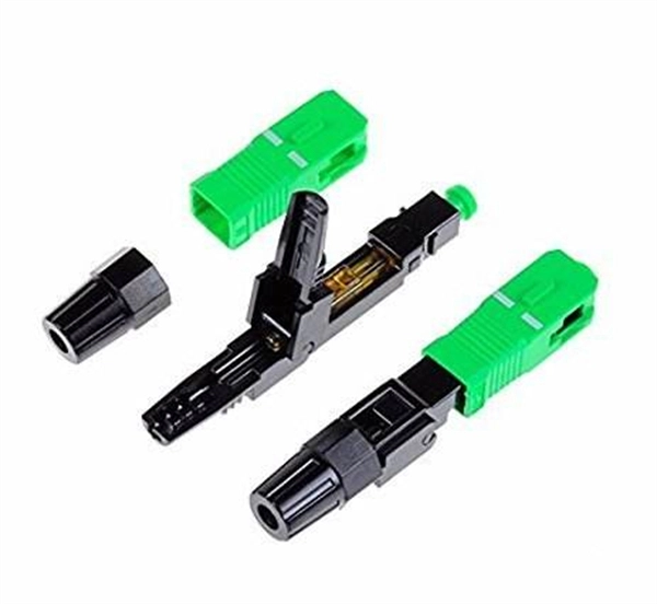
How much optical loss does a fiber optic cold connector typically experience
Generally, for single-mode connectors, the recommended insertion loss is below 0. Insertion loss, also known as attenuation, is the loss of optical power that occurs when light passes through a fiber optic connector. It is caused by factors such as misalignment, air gaps, and imperfections in the connector components. This article explores various connector types—such as SC, LC, FC, ST, APC, and UPC—and analyzes how their design and polishing affect IL and RL performance. Insertion Loss (IL): Measures the. Fiber loss, also called fiber optic attenuation or attenuation loss, refers to the loss of signal between input and output.
-

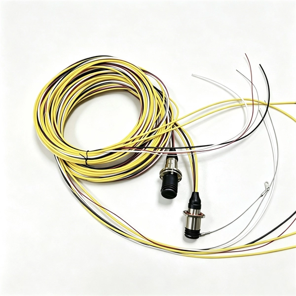
Which type of pigtail fiber suffers the least loss
One of the key advantages of LC pigtails is their low insertion loss, which ensures minimal signal degradation during transmission. Executive Summary: A fiber optic pigtail is one of the most commonly specified yet least understood components in structured cabling. Get the wrong connector type, the wrong polish, or skip proper fusion splicing technique—and you're looking at elevated signal loss, increased back reflection, and a. A fiber optic pigtail is a short length of optical fiber —typically 0. 5m to 2m—that has a factory-terminated connector on one end and bare fiber on the other end. For non-permanent connections, one can also use fiber connectors (see below). Figure 1:. They were all the wrong polish type. The network failed during testing. I've seen every kind of setup — from data centers to.