 Guide
Guide RRU Installation and Hardware Guide
It describes the appearance and functions of the RRU, and outlines the steps for installing the RRU units, connecting the power and optical cables, and properly grounding the equipment.
 Guide
Guide Changes in RRU5909&RRU5309&RRU5309w&RRU3959a
There are different types of optical modules which are configured depending on the actual application scenarios, see CPRI Fiber Optic Cable in 3900 Series Base Station Cables.
 Guide
Guide Exhibit 8 Manuals
The 1 and 2 interfaces provide connections to optical cables for traffic and timing signals between the RRU and the main unit. A Small Form-Factor Pluggable (SFP) is used to connect the optical cable to
 Guide
Guide RRU5517t Hardware Description
Explore the Huawei RRU5517t Hardware Description. This guide covers RRU introduction, functions, technical specifications, ports, indicators, cables, and auxiliary devices for SRAN17.1 and later versions.
 Guide
Guide Installation Guide
Lower the pullers of two optical modules, insert one optical module into the CPRI0 port on the RRU and the other optical module into the CPRI port on the BBU, and raise the pullers, as shown in Figure 7-25.
 Guide
Guide EN / ACS880 regenerative rectifier control program Firmware
If the control unit of the regenerative rectifier unit is powered from the faulty module, install an extension to the wiring and connect it to one of the remaining modules.
 Guide
Guide HUAWEI RRU USER MANUAL Pdf Download | ManualsLib
The single RRU can be installed on a metal pole or wall. 3.4.1 Installing a Single RRU This describes how to install a single RRU module and its mounting plate.
 Guide
Guide HUAWEI ERRU SERIES QUICK INSTALLATION MANUAL Pdf
Lower the puller of the optical module, insert an optical module into the CPRI0/IR0 port on the RRU, and raise the puller. CAUTION • The optical modules to be installed must match CPRI rates.
 Guide
Guide Microsoft PowerPoint
After the cables are installed on the RRU, insert the waterproofing fillers into the idle cable holes. When wrapping the waterproofing tape, apply even force to extend the tape until the width of the tape is 1/2
 Guide
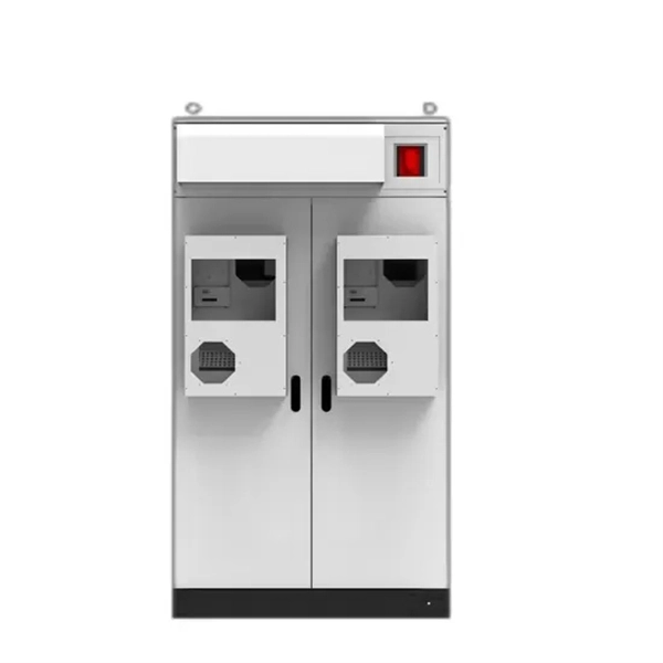
Guide EN / ACS880-907 regenerative rectifier units hardware manual
The drawing below represents the grounding of the control cabling when connecting to a terminal block inside the cabinet. The grounding is done in the same way when connecting directly to
 Guide
Guide eRRU Quick Installation Guide (V100R005C10_04) (PDF)-EN.pdf
Connect the M6 OT terminal at one end of the PGND cable to the ground terminal at the bottom of the eRRU and the M8 OT terminal at the other end to the external ground bar.
 Guide
Guide RRU RFD01F Series Installation Manual | Manualzz
Get the installation manual for the RRU RFD01F Series, a radio access network device for LTE networks. This manual explains how to install and maintain this device.