-
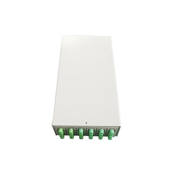
Should the cable management rack be installed in the front or the back
Leave space for cable management —especially in the back. Ensure front-to-back airflow by leaving gaps or using filler panels. This method helps maintain neatness and accessibility within the rack while ensuring efficient airflow and ease of maintenance. Both overhead and under floor pathways should be designed to support the weight of cables in the initial installation and it should also facilitate the addition of future cables. With proper design and structured tools, it helps organize cables, ensure stable signal transmission, simplify maintenance, and improve overall system. Here are some best practices for rack placement: Implementing hot and cold aisle containment is a fundamental strategy for improving airflow and cooling efficiency. The racks should be positioned in a way that optimizes.
-
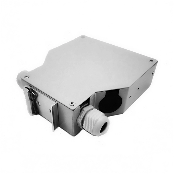
Fixing bracket on the back of the distribution box
How to install the mounting bracket? Many engineers don't know how to install this accessory. With the latest design, it can be confusing. Mounting bracket is a flexible structure, which makes it easy to adjust or replace the electrical components. All the components, wires and connections are under the protective cover due to the same height. The BBT-HF telescoping bracket, used with the BBA and BBA-4 box mounting brackets, provides an extremely flexible, fast rough-in solution. more Charlie DIYte (CharlieDIYte) tagged products below. Make sure the walls are strong enough to bear the weight of the box and electrical equipment. Ground. Electrical box screw mounts broke, can it be fixed without tearing up wall? I was unplugging an appliance in the kitchen when the whole outlet pulled out of the wall. Second photo shows my temp.
-
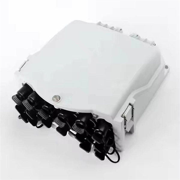
The power cable enters from the bottom of the distribution box
Cables can enter the structure from the floor (bottom entry) or from above (top entry. ) Distribution structures divide and send power to branch circuit protection devices and then to branch circuits to power downstream loads. Power. When installing a new overhead combination service for a residential service replacement we were told by the EI that we could not install our romex cables coming from under the house in a single 2" pipe approx. The scope of the article includes electrical requirements related to: Below is a complete overview. Once the box is securely in place, it's time to bring in the cables that will carry current from the main panel. Escape will cancel and close the window. Power from the utility company is typically delivered through three large conductors, which may enter the house overhead or underground. Overhead service. Fixed to a wall—This is a common approach for small electrical distribution boards. For bottom entry, the floor can incorporate a trench or false floor, which is often simpler since it provides.
[PDF Version]
-
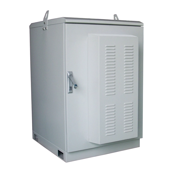
Spacing of the side of the distribution box
Side clearance: There should be a minimum of 30 inches of clearance from the sides of all electrical equipment, but in no case less than the width of the equipment itself. This is referred to as the side-to-side working space. In industrial power distribution systems, cable distribution boxes (also known as power distributor boxes, distribution electrical boxes, or electrical power distribution boxes) are the core hub of power transmission, branching, and protection. Its layout directly affects the efficiency of the. NEC Article 314 establishes requirements for the installation and use of electrical boxes, conduit bodies, fittings, and handhole enclosures. NEC Article 408. Boxes distribute low currents in an area equipped with 1 to 12 RJ 45 sockets. They centralise connections to ensure flexibility and that the installation is up to date.
[PDF Version]
-
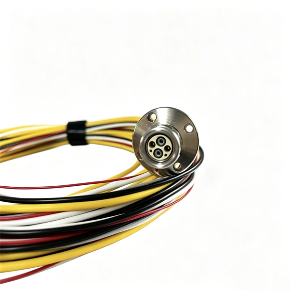
Working principle of dual-axis fiber optic collimator
The basic working principle is that the fiber's end face is placed at or near the focal point of a lens. Light exiting the fiber spreads out; if positioned correctly relative to the lens, the lens converts that diverging cone into a beam with minimal divergence (a collimated . Fiber optic collimators (also called fiber-optic collimators) are crucial optical components that convert the diverging output from an optical fiber into a collimated (parallel) beam, or conversely focus light from free space into a fiber. They can also be used in reverse to focus light into a fiber. In principle, a simple collimation lens (see Figure 1) is sufficient for that purpose. However, the fiber end has to be firmly fixed at a distance from the lens which is approximately equal. Thorlabs offers a variety of fiber collimation and coupling solutions.
[PDF Version]
-
What is the working principle of galvanized cable trays
At its core, a galvanized cable tray is a steel‑based cable support system that has been coated with zinc to protect against rust and oxidation. This protective layer makes the tray far more resistant to corrosion than untreated steel and extends the system's lifespan in harsh. For industrial and commercial installations, galvanized cable tray systems offer unbeatable durability, corrosion resistance, and long‑term cost‑effectiveness compared to many other options. Why Choose Hot-Dip. maintain spacing or to keep cables in place when the tray is ect the minimum bend ra-dius for cables as they exit the bottom of the cable tray. The mechanical and electrical characteristics, tests, certifications, overall quality management, recommendations mentioned in this technical guide only apply to our own cable management ranges and cannot under any circumstances be transposed to si osure, overheating or. Cable trays create a clear pathway for wires. They keep cables away from danger and allow proper air flow.
[PDF Version]
-
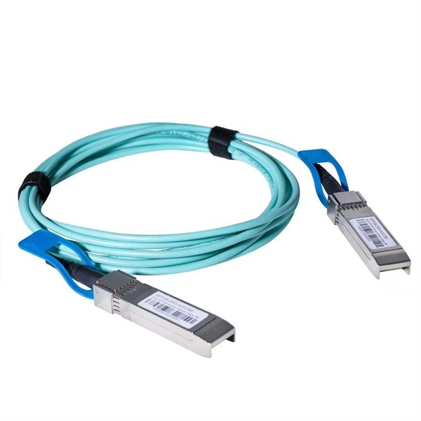
Working principle of passive wavelength division multiplexer
The working principle of WDM technology is based on the properties of the optical spectrum. In a WDM system, multiple light sources generate optical signals at different wavelengths and mix these signals together. Its main working principles include the following aspects: Wavelength division multiplexing (WDM). Abstract Wavelength division multiplexing or WDM allows the combining of a number of independent information-carrying wavelengths onto the same fiber, because of the wide spectral region in which optical signals can be transmitted efficiently.