-
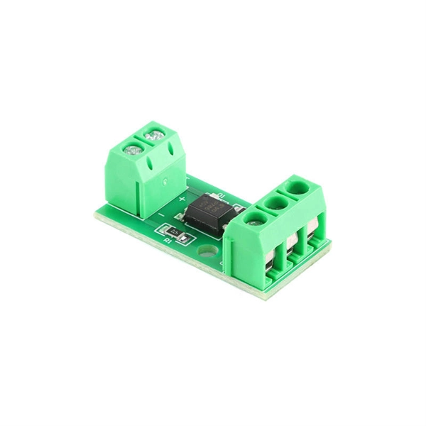
What is the relay protection time difference
The IEC standard for relay coordination recommends time grading between relays based on fault current magnitude and operating characteristics. For overcurrent protection, a minimum time margin of 0. 5 seconds is often maintained between primary and backup relays. The principle is to grade the operating times of the relays in such a way that the relay closest to the fault spot operates first. In order for the relay to operate, it needs to be energized. This energy can be provided by battery sets (mostly) or by the monitored circuit itself. In which case you use any of them. Are there any benefits of using one. A protection relay is a crucial component of electrical systems that safeguard infrastructure, employees, and equipment from electric problems and malfunctions. The relay settings that are selected are often a compromise in order to cope with both overload and. In electrical engineering, a protective relay is a relay device designed to trip a circuit breaker when a fault is detected.
[PDF Version]
-

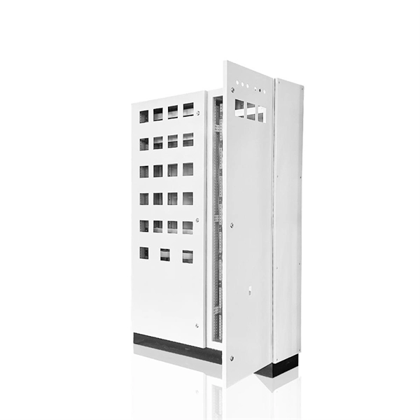
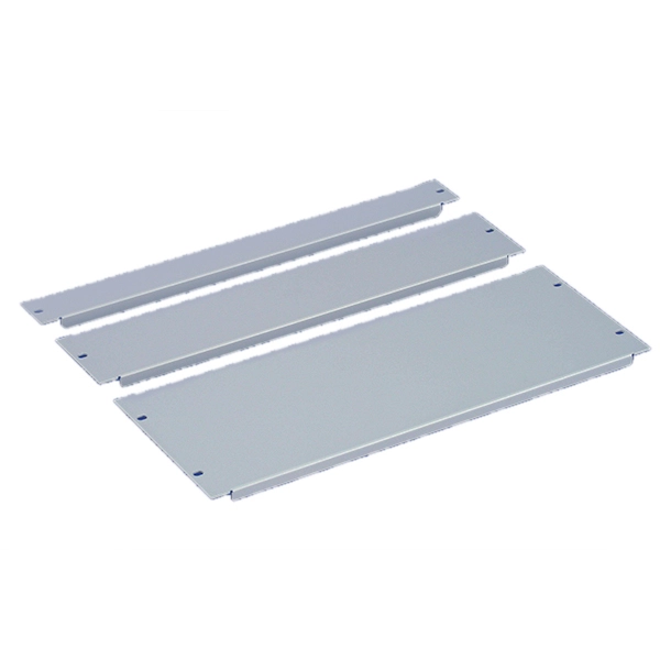
What type of copper is used for the small busbar in a high-voltage switchgear
ETP copper, known as C11000, is widely used for busbars due to its high conductivity and affordability. Although cost-effective, ETP copper is prone. Copper busbars are essential components in electrical power distribution systems, widely used in switchgear, substations, panel boards, and industrial electrical installations. They are easy to install and offer a high surface area, which is great for heat dissipation. Their design allows for simple connections and can be easily. The most common type of copper used. With a minimum copper content of 99. aluminum's 61%) but aluminum providing significant weight reduction (66% lighter) and cost savings (30-50% cheaper).
-
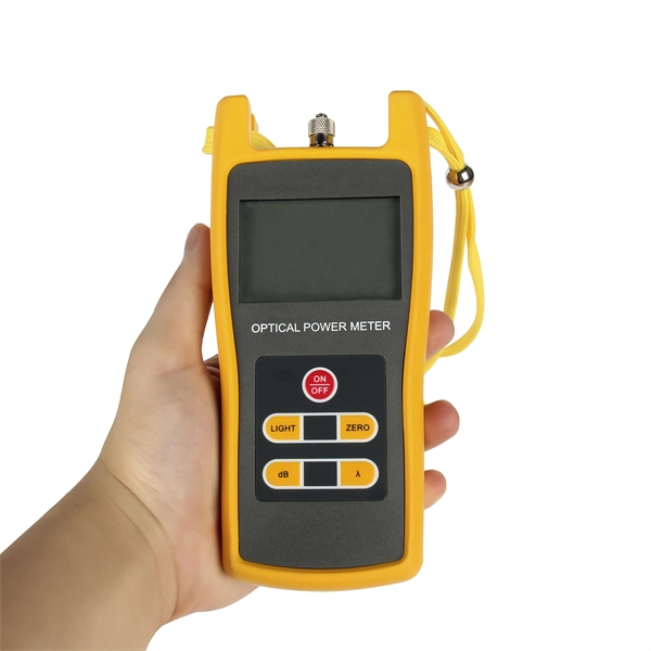
What is the loss of a 12-channel splitter
A splitter will have approximately 3. The theoretical loss assumes perfect splitting with no imperfections. In practice, losses are slightly higher due to: Insertion loss tells you how much weaker the signal becomes after passing through the splitter. Let's say you have a laser output at 0 dBm (which is 1 milliwatt of optical power). If you experience signal issues while using a splitter, you may need to install a distribution amplifier or a preamplifier. For example, for the loss (attenuation) in a segment of optical fiber we have the value at the input of the segment and at its output.
-
What ports does a core switch have
Core switches are equipped with advanced port configurations to handle high-bandwidth requirements. They often feature: 10G SFP+ for high-speed connectivity. The core switch is the most important piece of hardware in this infrastructure, acting as the high-speed, central nervous system that ensures all parts of the network can communicate. If it is a small local area network with several computers, a small switch with 8 ports can be called a core switch. Most of the network ports are Gigabit Ethernet or 100M Ethernet ports. The main function is to access user data or aggregate switch data of some access layers. Configure VLAN simple routing protocol and some simple SNMP functions. RJ45 ports serve access-layer copper connections; SFP/SFP+ ports enable flexible 1G/10G uplinks; SFP28 delivers 25G for modern data centers; QSFP+ and QSFP28 support high-density 40G/100G spine–leaf. A core switch is a high-capacity, high-performance Layer 3 switch positioned at the physical backbone of an enterprise network. Engineered to aggregate massive volumes of data from distribution switches, it provides ultra-low latency and maximum throughput to ensure uninterrupted routing and packet.
[PDF Version]
-
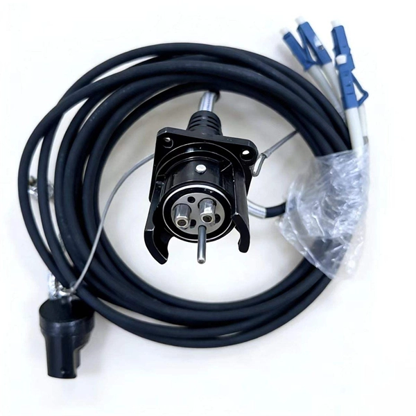
What does a multi-core fiber optic adapter look like
MPO fiber optic connector is a multi-core multi-channel plug-in connector. It is characterized by a rectangular ferrule with a nominal diameter of 6. 7mm on the end face of the ferrule to position and align the. A Multi-core Fiber (MCF) Coupling Connector is a high-precision optical connector engineered to align and connect multi-core optical fibers., two fiber connectors) such that light can reliably pass from one to the other with minimal insertion loss and maximum return loss. These multi-fiber connectors stand out by enabling simultaneous multi-core fiber connections through a single interface, a feature that directly addresses the industry's pressing needs for higher bandwidth and space-efficient cabling. The number of fibers changes how you set up your network and how much you can grow it later. Picking the right MPO/MTP connectors.
-
What is a direct-fusion optical cable line
It is a technique that uses controlled heat to permanently fuse two optical fiber ends together. Unlike mechanical splicing, which relies on alignment sleeves and index-matching gel, this thermal approach creates a continuous glass path between fibers. There are two ways of fiber optic cable termination, namely, connectors and splicing. This guide reveals the secrets to fusion splicing with little fluff—just proven, straightforward techniques refined from years of work in the. Fiber optic cabling is a critical component of modern telecommunications infrastructure, owing to its high bandwidth, reliability, durability, and cost-effectiveness. Fusion splicing stands out as a superior technique for joining optical fibers, offering a seamless, low-loss connection that is crucial for reliable fiber optic networks. Regardless of the type of fiber network you're deploying, be it for telecom, enterprise data centers, or smart city infrastructure, fusion splicing provides the benefits of. This is where fiber optic cable splicing—the process of creating a permanent, high-performance join between two fiber ends—becomes critical.
[PDF Version]
-
What are the uses of special optical cables in the field
While standard fiber optic cables serve well in general communication networks, specialty cables offer unique features, such as enhanced performance in extreme environments, increased data capacity, or compatibility with specific wavelengths of light. At its most basic, a fiber optic cable is composed of glass threads (optic fibers), each of which can transmit messages. Optical fibers have transformed how we communicate, connect, and transmit data. Among these, special optical fibers stand out for their tailored properties, enabling applications beyond traditional telecommunications. As technology advances, the demand for specialized optical cables has grown, leading to the development of various specialty fiber cables. HOC (Hone Optical Communications) special fiber optic cable means the optical cables used in special areas or need special structure and materials to meet the application environment. It is designed to transmit data in the form of light signals over long distances with minimal signal loss.
[PDF Version]
-

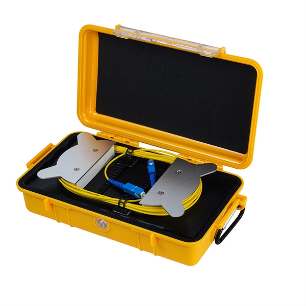
What is the fiber optic splice tray in the optical distribution box
• Splice Tray: This compartment is designed for fiber splicing and storage. It features slots or holders that secure spliced fibers, protecting them from bending, physical damage, or external stress. What is a Fiber Splice Tray Used for? With the increasing development of optical fiber networks, optical fiber terminals using fusion splicing or mechanical fusion have become common. Because optical fibers are sensitive to pulling, bending, and crushing forces, use fiber splice trays to provide. With the growth of FTTH, FTTx, and telecom fiber networks, the management of fiber optic splicing plays an increasingly important role in network reliability, performance, and maintainability. Inside splice closures, cabinets, and distribution frames, dozens or even hundreds of fibers need to be. Fiber Distribution Boxes (FDBs) are critical components in modern telecommunications infrastructure, particularly in fiber optic networks. Typically made from durable materials like plastic or.
[PDF Version]
-
What signals can fiber optic sensors detect
Unlike traditional electrical sensors (e., proximity switches or pressure sensors), it operates not by electrical signals but by detecting changes in light—such as intensity, wavelength, or polarization direction—to measure an object's position, distance, temperature, or even. Unlike traditional electrical sensors (e. The basic working principle is that when the light signal passes through the optical fiber, parameters such as light intensity, wavelength, and phase will be affected by the. Fiber optic current sensors are revolutionizing the way electrical currents are measured, providing high sensitivity, immunity to electromagnetic interference (EMI), and the ability to function in harsh environments. The fiber optic sensor has an optical fiber connected to a light source to allow for detection in tight spaces or where a small profile is beneficial. Depending on the. A sensor is a device that measures a physical quantity and converts it into a signal.
[PDF Version]
-
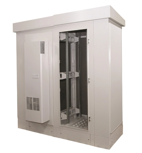
What are the main components of an optical distribution box
ODF, also known as optical distribution frame or fiber optic patch panel, is a critical device used in optical communication for managing and distributing optical fibers. They provide efficient fiber optic management, connectivity, and protection. It is usually a compact and structured framework composed of a steel shell and internal fiber splice tray as the main. This complete guide explores everything you need to know about ODFs — from their structure, types, and key components, to installation best practices and modern design trends. Whether you're building a central office, data center, or FTTx distribution network, understanding the right ODF.
-
What type of copper is used in network patch panels
Twisted-pair copper patch panels are built to a certain Ethernet specification, such as Cat 5e, Cat 6, or Cat 6a, and though they are backwards compatible, use different gauges of copper wiring to facilitate the greater bandwidth and shielding of the higher categories. In each case, the patch panel. Today, various styles of copper patch panels can be found in the market, such as shielded or unshielded patch panel, flat or angled patch panel, etc. Their design, material, and compliance directly affect signal integrity, insertion loss, crosstalk, manageability, and fire safety.