-
What is the relay protection time difference
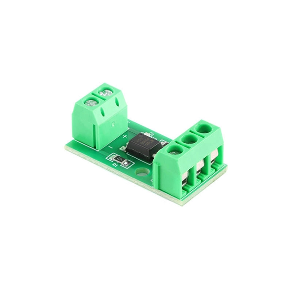
The IEC standard for relay coordination recommends time grading between relays based on fault current magnitude and operating characteristics. For overcurrent protection, a minimum time margin of 0. 5 seconds is often maintained between primary and backup relays. The principle is to grade the operating times of the relays in such a way that the relay closest to the fault spot operates first. In order for the relay to operate, it needs to be energized. This energy can be provided by battery sets (mostly) or by the monitored circuit itself. In which case you use any of them. Are there any benefits of using one. A protection relay is a crucial component of electrical systems that safeguard infrastructure, employees, and equipment from electric problems and malfunctions. The relay settings that are selected are often a compromise in order to cope with both overload and. In electrical engineering, a protective relay is a relay device designed to trip a circuit breaker when a fault is detected.
[PDF Version]
-

What type of copper is used for the small busbar in a high-voltage switchgear
ETP copper, known as C11000, is widely used for busbars due to its high conductivity and affordability. Although cost-effective, ETP copper is prone. Copper busbars are essential components in electrical power distribution systems, widely used in switchgear, substations, panel boards, and industrial electrical installations. They are easy to install and offer a high surface area, which is great for heat dissipation. Their design allows for simple connections and can be easily. The most common type of copper used. With a minimum copper content of 99. aluminum's 61%) but aluminum providing significant weight reduction (66% lighter) and cost savings (30-50% cheaper).
-
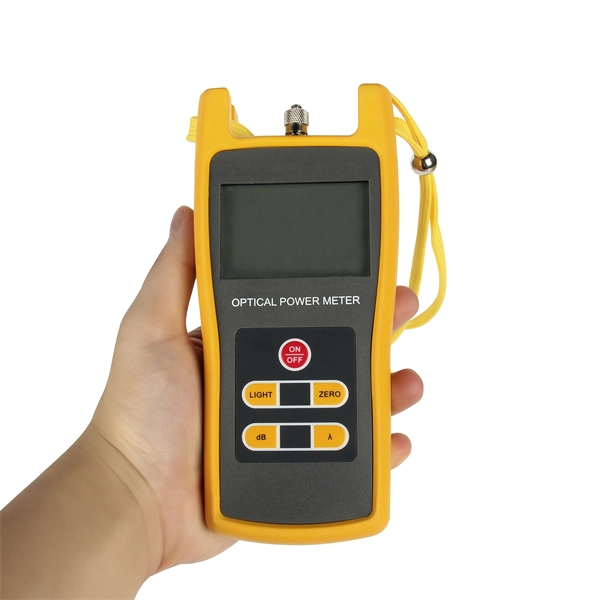
What is the loss of a 12-channel splitter
A splitter will have approximately 3. The theoretical loss assumes perfect splitting with no imperfections. In practice, losses are slightly higher due to: Insertion loss tells you how much weaker the signal becomes after passing through the splitter. Let's say you have a laser output at 0 dBm (which is 1 milliwatt of optical power). If you experience signal issues while using a splitter, you may need to install a distribution amplifier or a preamplifier. For example, for the loss (attenuation) in a segment of optical fiber we have the value at the input of the segment and at its output.
-
What ports does a core switch have
Core switches are equipped with advanced port configurations to handle high-bandwidth requirements. They often feature: 10G SFP+ for high-speed connectivity. The core switch is the most important piece of hardware in this infrastructure, acting as the high-speed, central nervous system that ensures all parts of the network can communicate. If it is a small local area network with several computers, a small switch with 8 ports can be called a core switch. Most of the network ports are Gigabit Ethernet or 100M Ethernet ports. The main function is to access user data or aggregate switch data of some access layers. Configure VLAN simple routing protocol and some simple SNMP functions. RJ45 ports serve access-layer copper connections; SFP/SFP+ ports enable flexible 1G/10G uplinks; SFP28 delivers 25G for modern data centers; QSFP+ and QSFP28 support high-density 40G/100G spine–leaf. A core switch is a high-capacity, high-performance Layer 3 switch positioned at the physical backbone of an enterprise network. Engineered to aggregate massive volumes of data from distribution switches, it provides ultra-low latency and maximum throughput to ensure uninterrupted routing and packet.
[PDF Version]
-
What does a multi-core fiber optic adapter look like
MPO fiber optic connector is a multi-core multi-channel plug-in connector. It is characterized by a rectangular ferrule with a nominal diameter of 6. 7mm on the end face of the ferrule to position and align the. A Multi-core Fiber (MCF) Coupling Connector is a high-precision optical connector engineered to align and connect multi-core optical fibers., two fiber connectors) such that light can reliably pass from one to the other with minimal insertion loss and maximum return loss. These multi-fiber connectors stand out by enabling simultaneous multi-core fiber connections through a single interface, a feature that directly addresses the industry's pressing needs for higher bandwidth and space-efficient cabling. The number of fibers changes how you set up your network and how much you can grow it later. Picking the right MPO/MTP connectors.
-
What is a direct-fusion optical cable line
It is a technique that uses controlled heat to permanently fuse two optical fiber ends together. Unlike mechanical splicing, which relies on alignment sleeves and index-matching gel, this thermal approach creates a continuous glass path between fibers. There are two ways of fiber optic cable termination, namely, connectors and splicing. This guide reveals the secrets to fusion splicing with little fluff—just proven, straightforward techniques refined from years of work in the. Fiber optic cabling is a critical component of modern telecommunications infrastructure, owing to its high bandwidth, reliability, durability, and cost-effectiveness. Fusion splicing stands out as a superior technique for joining optical fibers, offering a seamless, low-loss connection that is crucial for reliable fiber optic networks. Regardless of the type of fiber network you're deploying, be it for telecom, enterprise data centers, or smart city infrastructure, fusion splicing provides the benefits of. This is where fiber optic cable splicing—the process of creating a permanent, high-performance join between two fiber ends—becomes critical.
[PDF Version]
-
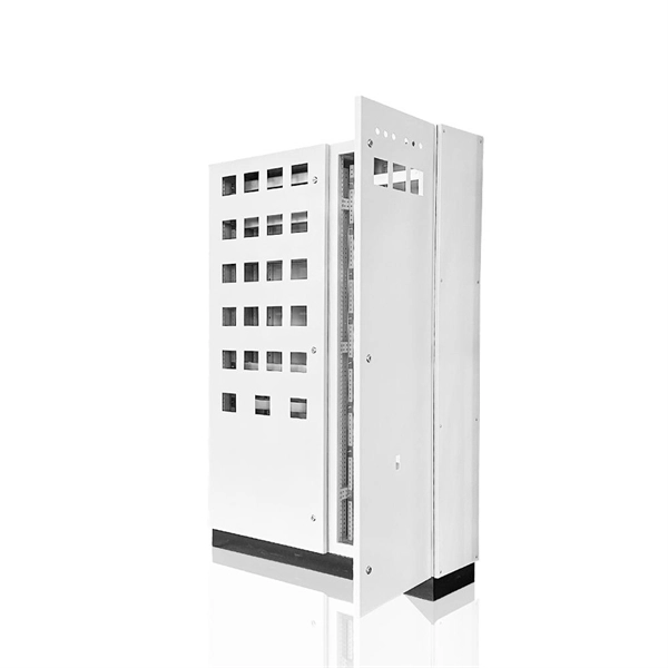
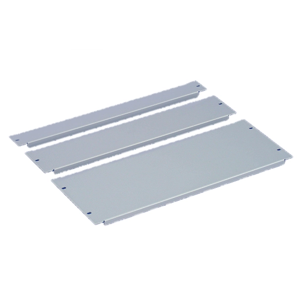
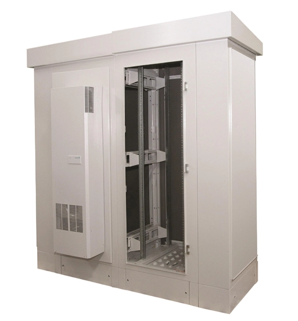
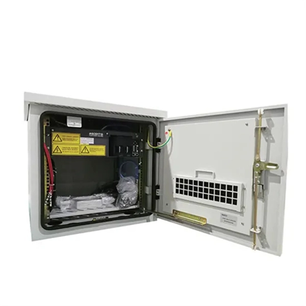
What is the appropriate thickness for a secondary distribution box
Therefore, the thickness of the sheet metal of the cabinet body of the power electrical distribution box is usually not less than 1. 0mm or thicker, may be. Requirements for concrete enclosures, required when installing a secondary enclosure in an area subject to vehicular traffic. In no case shall the volume of the box, as calculated in 314. Their dimensions are generally around 2 inches wide by 4 inches tall, with depths varying from 1-1/2 inches to 3-1/2 inches. Just like travelers need clear pathways and safety protocols, your electrical circuits need proper management to prevent chaos. 5mm thick cold-rolled steel plates can be used.
-
What is the failure rate of AI servers
AI agents fail between 70% and 95% of the time in real-world settings, and performance drops even further when tasks are repeated multiple times in a row. Failures compound fast in multi-agent systems. If each agent succeeds only 70% of the time, a three-agent chain succeeds just. While a precise percentage of all started technology projects that are AI projects is not readily available, the increasing investment, adoption rates, and the range of project costs indicate a substantial number of AI initiatives are being undertaken. Multiple sources indicate a high failure rate. 70–80% of AI Projects Fail After Pilot. Here's Why (2026 Data) Updated for 2026 based on enterprise AI benchmark data. Most AI systems don't fail in development. Studies and surveys report that the vast majority of corporate AI initiatives either stall or fail to produce significant business value () (). And in simulated office environments, LLM-driven AI agents get multi-step tasks wrong. A staggering 95% of generative AI pilots at companies are failing, according to a recent report published by MIT's NANDA initiative.
[PDF Version]
-
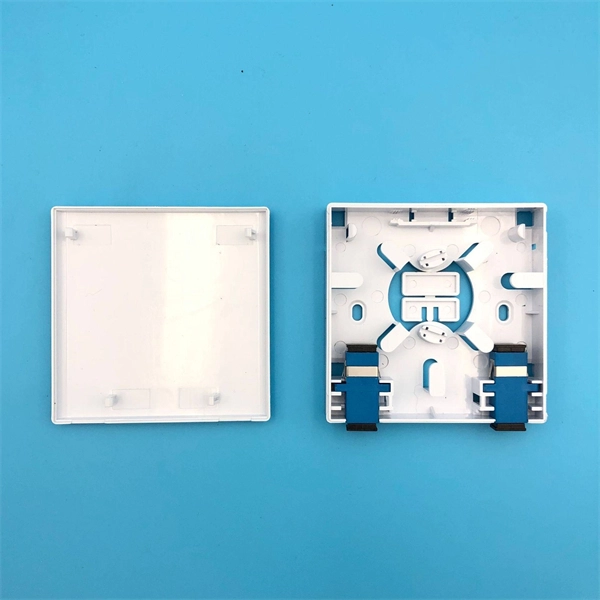
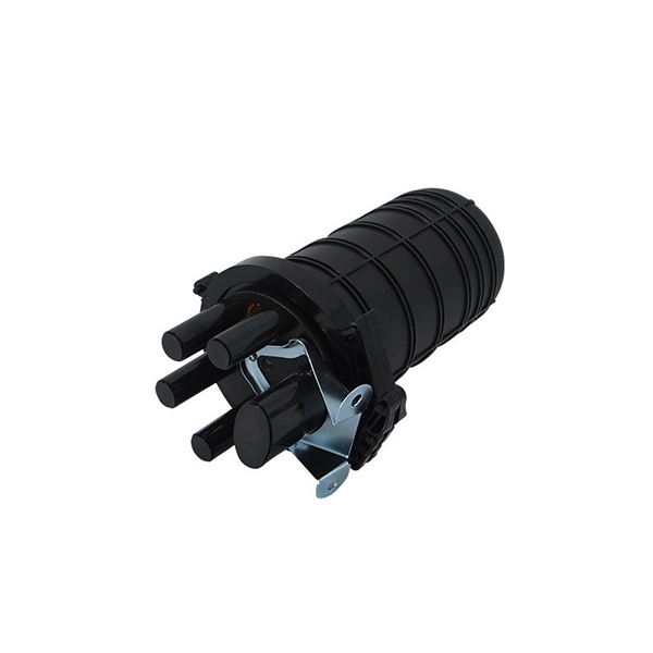
What are the main components of an optical distribution box
ODF, also known as optical distribution frame or fiber optic patch panel, is a critical device used in optical communication for managing and distributing optical fibers. They provide efficient fiber optic management, connectivity, and protection. It is usually a compact and structured framework composed of a steel shell and internal fiber splice tray as the main. This complete guide explores everything you need to know about ODFs — from their structure, types, and key components, to installation best practices and modern design trends. Whether you're building a central office, data center, or FTTx distribution network, understanding the right ODF.
-
What are optical cable termination and splicing
To begin, the standard definition of splicing in optical fiber is joining two fiber optic cables together. Both techniques have their advantages and are suited for different applications, but understanding which method to use can greatly impact the network's. The critical procedure of fiber optic termination and splicing is essential in ensuring a reliable, loss-free transmission in fiber optic systems. This guide aims to provide an in-depth understanding of fiber optic termination, types of fiber optic termination, splicing methods, and the. We terminate fiber optic cable two ways - with connectors that can mate two fibers to create a temporary joint and/or connect the fiber to a piece of network gear or with splices which create a permanent joint between the two fibers. For network managers and technicians, a poor splice can lead to significant signal degradation, network downtime, and costly troubleshooting.
[PDF Version]
-
What does intelligent PDU mean
An intelligent PDU is a smart device that distributes power while providing real-time monitoring and control. It allows users to monitor and control their power usage. There are two types of Power Distribution Units (PDUs), the basic type and the intelligent type.