-
How to remove the finished optical module
To safely remove an SFP module, follow these steps: Disable the port in your network device settings or power off the device to avoid electrical damage. Gently pull the module latch or release ring, depending on the module design. Whether you're upgrading bandwidth, replacing a faulty unit, or reconfiguring your topology, knowing. Take ESD protection measures when replacing optical modules. Preparation Before Installation 1. more FS N5570-48S6C is a 48-port Layer 3 Ethernet switch with Broadcom Trident3-X5 chips, offering 1. They enable high-speed connections between active equipment and allow system scalability without the need for full infrastructure replacement.
-

Optical module test power not adjusted too low
What does it mean if the transmitted power is too low? Low transmitted power can mean the connectors are dirty. Clean the connectors, check the module, and look at the fiber. If it still does not. Stable optical power is the foundation of every high-capacity optical transport system. Even minor deviations—whether too high, too low, or unstable—can impact signal integrity, trigger service alarms, or interrupt traffic on DWDM, OTN, or long-haul optical line systems. Because optical networks. The article Digital Diagnostic Function (DDM) For Optical Modules describes that DDM function can be used for real-time monitoring and fault location of the module's working status, in which the optical module's transmitting optical power and receiving optical power are the key parameters for. To test transmitted power in sfp optical modules, you use an optical power meter to get exact results. Many sfp modules also have DOM/DDM, which lets you see digital diagnostic monitoring data on network equipment. Built into modern SFP/SFP+/ SFP28 /QSFP family modules and standardized by SFF-8472, DDM/DOM exposes real-time values for the module's temperature, supply.
[PDF Version]
-
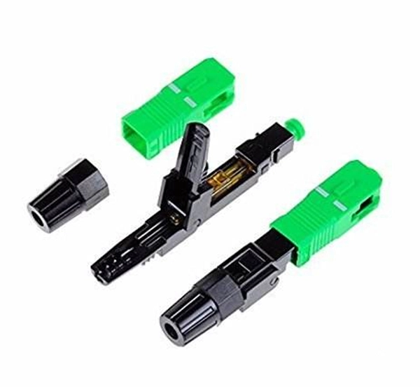
Plug an optical module into both ends of the optical fiber
Do not insert the optical module with optical fibers directly into an optical interface. From enterprise access networks to large-scale data centers, SFP modules allow network. In high-speed data networks, the seamless integration of fiber optic cables with SFP (Small Form-Factor Pluggable) modules is critical for reliable signal transmission. However, with a bit of guidance, the process is straightforward. This article will walk you through the necessary steps to ensure a successful connection. This optical transceiver tutorial will introduce how to install SFP module, how to remove SFP module, and give some insights on the operation precautions.
-
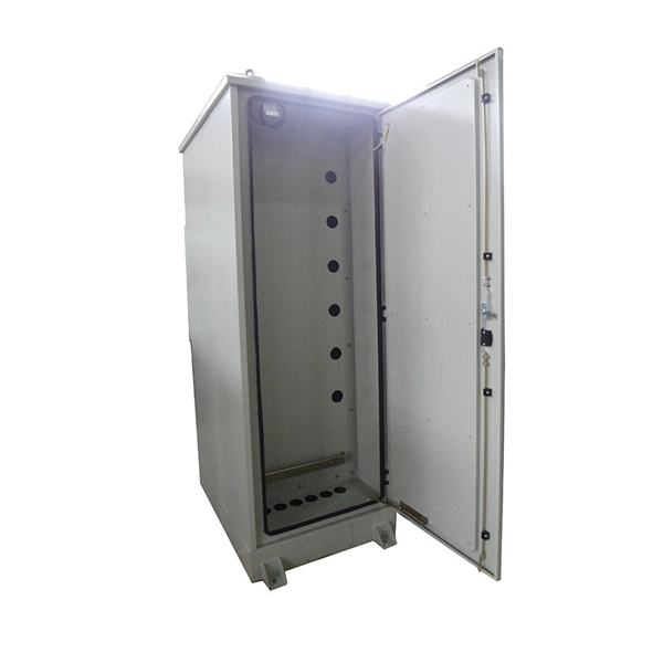
Function of optical module cage
Simply put, a fiber optic cage (also commonly called an optical transceiver cage or cage assembly) is a precision metal housing designed to securely hold, align, and connect an optical transceiver module to a printed circuit board (PCB). Understanding what a fiber optic cage is and its role is essential for anyone designing, deploying, or maintaining robust optical infrastructure. This guide delves deep into the purpose, function, types, and importance of these fundamental components, highlighting their synergy with optical. An optical cage system uses four rigid steel rods to mount optical components along a common optical axis. Cage systems are available with center-to-center rod spacings of 16 mm, 30 mm, or 60 mm so as to accommodate Ø1/2", Ø1", or Ø2" optics, respectively. Thorlabs provides an extensive selection. Optical Cage Systems are used to create optical setups in a variety of prototyping or university research applications.
[PDF Version]
-
Optical module bias adjustment
Typical optical modulators such as LN (Lithium Niobate) modulators, Mach- Zehnder modulators, and EA (Electro-absorption) modulators require the optimization of bias voltages. If the bias voltage is improperly adjusted, abnormal spectral peaks may occur and degrade optical. Optical line cards and modules demand high-integration and application-specific features for IQ modulator biasing. The DACx1416 is geared to provide a holistic and highly-optimized solution that requires minimal external components. It also addresses the specific requirements of all MZM. An optical modulator is a key device indispensable for optical communication that transforms the properties of light such as wavelength, intensity, and phase with electrical signals. For example, lithium niobate external modulators applied in fiber optic communication systems also need a. The Optilab BCB-4 is a compact bias control board designed to maintain the linear operating point of optical intensity modulators.
[PDF Version]
-
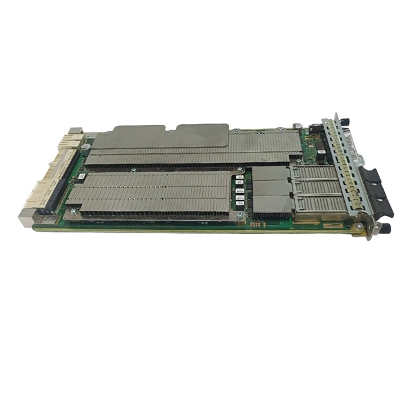
Optical Module Product Process
The optical module PCBA manufacturing process involves assembling optoelectronic devices and electronic components onto printed circuit boards. Through a series of processing steps, this manufacturing technique enables the conversion and transmission of optical signals into. The optical module is one of the core components of the optical fiber communication system and the most important part of the optical communication equipment. Its main function is to realize the conversion of optical and electrical signals. With the development of the Internet, the amount of. The Printed Circuit Board (PCB) at the heart of these modules is no longer a simple substrate but a highly engineered system. Increased complexity in chip functionality has resulted in a need for increased fabricati n complexity from III-V epitaxy, through wafer. With its world-beating line of optical devices, including semiconductor pumping lasers for long-distance optical-communications applications, gain chips and semiconductor amplifiers supporting data communications, power supplies for gas-sensing, etc.
[PDF Version]
-
How to remove a loose pull ring from an optical module
Gently pull the module latch or release ring, depending on the module design. To use an SFP optical module, first confirm that the host port is SFP-type. Figure 1 SFP Optical Module Installation. However, with the right approach and careful handling, you can safely remove a transceiver stuck in a switch without causing damage to your network equipment. There are two primary reasons why an SFP module might become stuck in a port: The SFP is wedged in the cage: This can occur due to slight. To connect an optical cable to an SFP module, use the appropriate patch cord (e. Once connected, verify that the port activity indicator is on and run diagnostic commands to check the module status. After removing the fiber jumper, insert a clean dust cover over it to protect the end face of the module.