-
Test Report on a New Vertical Cavity Surface Emitting Laser
Recent results on highly reliable 940nm multi-junction high power vertical-cavity surface-emitting lasers (VCSELs) are presented with target applications in depth sensing and Light Detection Ranging (LiDAR) markets. Vertical-cavity surface-emitting lasers (VCSELs) having a small aperture and operating in a single transverse mode (SM) are known to reach high relaxation oscillation frequencies of 30-90GHz and, thus, can offer intrinsic modulation bandwidth beyond 100GHz, once photon damping and electric. In this work, we present a high-performance vertical cavity surface emitting laser (VCSEL) based on a single-crystal CsPbBr 3 microplatelet, fabricated through a simple solution process and sandwiched between two distributed Bragg reflector (DBRs). Our innovation, the antireflective.
-
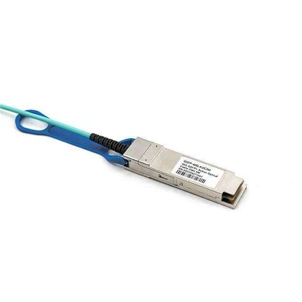
Columbia Vertical Cavity Surface Emitting Laser QSFP28
The surface emission from a bulk semiconductor at ultra-low temperature and magnetic carrier confinement was reported by Ivars Melngailis in 1965. The first proposal of short VCSEL was done by Kenichi Iga of Tokyo Institute of Technology in 1977. A simple drawing of his idea is shown in his research note. Contrary to the conventional Fabry-Perot edge-emitting semiconductor lasers, his invention comprises a short laser cavity less than 1/10 of the edge-emitting lasers vertical to a wafer s.
-
Cable vertical quota along cable tray
Cable Types: Only use conductors rated for open-air environments, such as Tray Rated (Type TC) or Metal-Clad (Type MC) cables. Cable tray types, fill rules for single-conductor and multiconductor cables, ampacity derating, separation requirements, and when to use tray vs conduit. Our free calculator helps you determine the correct tray size based on NEC and IEC standards. Follow these simple steps: Define Tray Dimensions: Enter the width and depth of your planned cable tray (in mm or inches). This is a description of how to select, install, and support these metal or plastic frames, on which electrical wires are installed. NEC 392 Fill Rules by Tray Type 3. Step-by-Step Calculation Example 4. Common Mistakes to Avoid NEC 392. This guide covers the critical steps, from selecting the right electrical cable tray and performing accurate cable fill calculations to managing a safe cable pull through and ensuring all bonding and grounding requirements are met. For licensed electricians, mastering these principles is essential.
[PDF Version]
-
Cost of Vertical Installation of Optical Cable
The cost to install fiber optic cable ranges from $1. 50 to $42 per foot, with installation costs accounting for 60-80% of total project expenses. According to the Fiber Broadband Association's 2025 report, median costs are $8 per foot for aerial builds and $18 per foot for. Fiber-optic cable pricing depends on whether you're purchasing materials alone or including complete installation. The main cost drivers include material type, run length, trenching or aerial work, and any required permits or inspections. This breakdown gives you real numbers to build better estimates. We'll show actual costs for.
-
Bending angle of vertical bend in cable tray
A box type cable tray vertical outside bend is a fitting used to change the direction of a cable tray system vertically, typically at a 90-degree angle, directing cables outward. How to calculate cable tray bends? Calculate the minimum required bend radius by multiplying the cable's outside diameter by its bending factor (e. Then, select a standard tray fitting (300mm, 450mm, etc. ) that matches or exceeds this value. Use this tool to estimate sloped section length, horizontal run requirement, cut marks, and installation feasibility. Measure this distance along the straight tray. 90° bend, Vertical Inner Bend, for all cable tray types of 50 mm side height. How to bend 90 degree of cable tray 3 line with the same distance :// • HOW TO BEND 90 DEGREE OF CABLE TRAY 3 LINE.
-
Spacing of vertical shaft cable tray fixing supports
Cable Management Tray Size: Choose a tray size that will hold the desired amount and length of cable. Support Spacing: Remember the NEC requires no more than 4 feet of support spacing. The National Electrical Code is a set of principles designed to promote public safety and welfare, as well as safeguard public health by regulating the design and operation of electrical facilities and. Article Summary: A compliant cable tray installation requires a thorough understanding of NEC Article 392, proper structural support, and precise installation techniques. This guide covers the critical steps, from selecting the right electrical cable tray and performing accurate cable fill. maintain spacing or to keep cables in place when the tray is ect the minimum bend ra-dius for cables as they exit the bottom of the cable tray. Proper installation can significantly reduce electromagnetic interference, prevent fire hazards, and improve overall efficiency. Clause 522-08-04 Where conductors or cables are not supported.
[PDF Version]