-

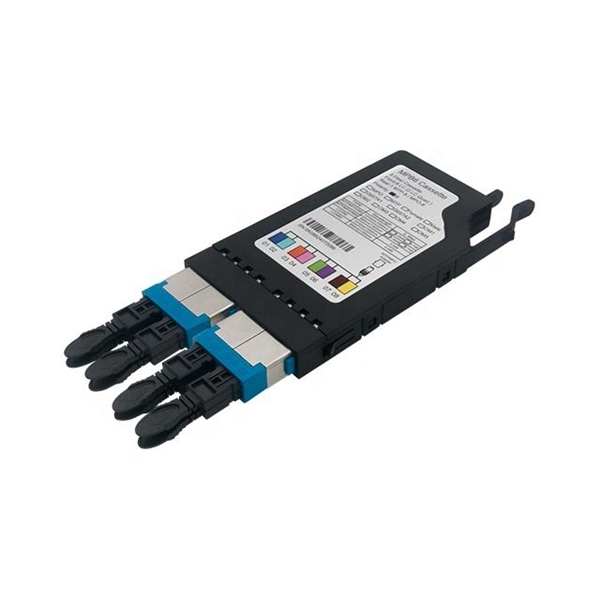
Chilean Quality Assured Vertical Cavity Surface Emitting Laser QSFP
The surface emission from a bulk semiconductor at ultra-low temperature and magnetic carrier confinement was reported by Ivars Melngailis in 1965. The first proposal of short VCSEL was done by Kenichi Iga of Tokyo Institute of Technology in 1977. A simple drawing of his idea is shown in his research note. Contrary to the conventional Fabry-Perot edge-emitting semiconductor lasers, his invention comprises a short laser cavity less than 1/10 of the edge-emitting lasers vertical to a wafer s.
-
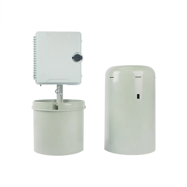
Columbia Vertical Cavity Surface Emitting Laser QSFP28
The surface emission from a bulk semiconductor at ultra-low temperature and magnetic carrier confinement was reported by Ivars Melngailis in 1965. The first proposal of short VCSEL was done by Kenichi Iga of Tokyo Institute of Technology in 1977. A simple drawing of his idea is shown in his research note. Contrary to the conventional Fabry-Perot edge-emitting semiconductor lasers, his invention comprises a short laser cavity less than 1/10 of the edge-emitting lasers vertical to a wafer s.
-
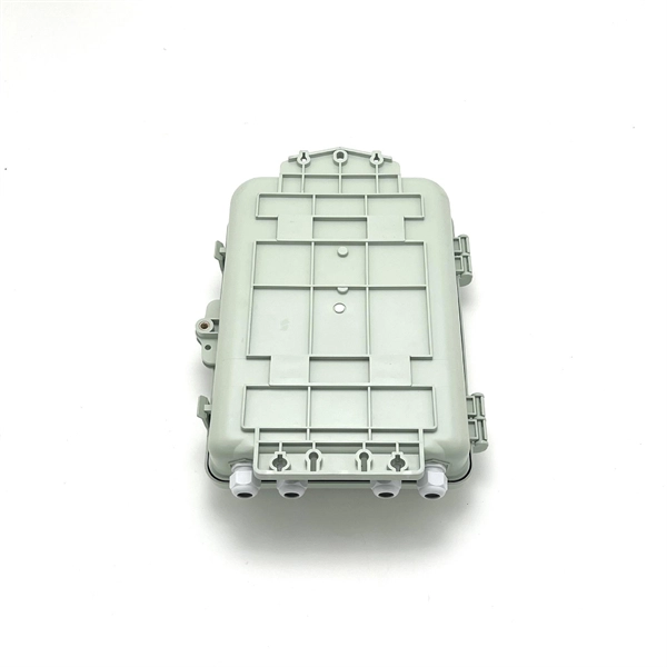
How to insert cables into the holes of a vertical cable tray
Splice plates are the most widely used method for connecting cable tray sections in straight runs. Choosing the right one depends on project conditions, load. Article Summary: A compliant cable tray installation requires a thorough understanding of NEC Article 392, proper structural support, and precise installation techniques. Treating them like horizontal systems leads to unsafe, hard-to-service railings and risers. Picture this: the deck is framed, posts are solid, and you have committed to a vertical cable railing, but as soon. Infill rails should be cut so the space between pickets, cables and posts should all appear to be consistent.
-
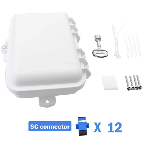
Vertical circuit of distribution box
Larger commercial, public, and industrial installations generally use three-phase supplies, with distribution boards which have twin vertical rows of breakers. Larger installations will often use subsidiary distribution boards.OverviewA distribution board (also known as panelboard, circuit breaker panel, breaker panel, electric panel, fuse box or DB box) is a component of an that divides an electrical power feed into subsidiary. North American distribution boards are generally housed in enclosures, with the positioned in two columns operable from the front. Some panelboards are provided with a door covering th. This picture shows the interior of a typical distribution panel in the United Kingdom. The three incoming phase wires connect to the busbars via a main switch in the centre of the panel. On each side of the panel are two.
-
Spacing of vertical shaft cable tray fixing supports
Cable Management Tray Size: Choose a tray size that will hold the desired amount and length of cable. Support Spacing: Remember the NEC requires no more than 4 feet of support spacing. The National Electrical Code is a set of principles designed to promote public safety and welfare, as well as safeguard public health by regulating the design and operation of electrical facilities and. Article Summary: A compliant cable tray installation requires a thorough understanding of NEC Article 392, proper structural support, and precise installation techniques. This guide covers the critical steps, from selecting the right electrical cable tray and performing accurate cable fill. maintain spacing or to keep cables in place when the tray is ect the minimum bend ra-dius for cables as they exit the bottom of the cable tray. Proper installation can significantly reduce electromagnetic interference, prevent fire hazards, and improve overall efficiency. Clause 522-08-04 Where conductors or cables are not supported.
[PDF Version]