-
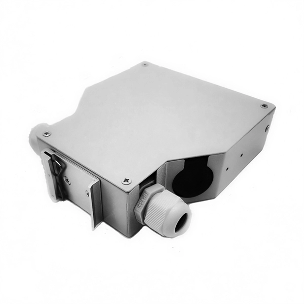
Fixing bracket on the back of the distribution box
How to install the mounting bracket? Many engineers don't know how to install this accessory. With the latest design, it can be confusing. Mounting bracket is a flexible structure, which makes it easy to adjust or replace the electrical components. All the components, wires and connections are under the protective cover due to the same height. The BBT-HF telescoping bracket, used with the BBA and BBA-4 box mounting brackets, provides an extremely flexible, fast rough-in solution. more Charlie DIYte (CharlieDIYte) tagged products below. Make sure the walls are strong enough to bear the weight of the box and electrical equipment. Ground. Electrical box screw mounts broke, can it be fixed without tearing up wall? I was unplugging an appliance in the kitchen when the whole outlet pulled out of the wall. Second photo shows my temp.
-
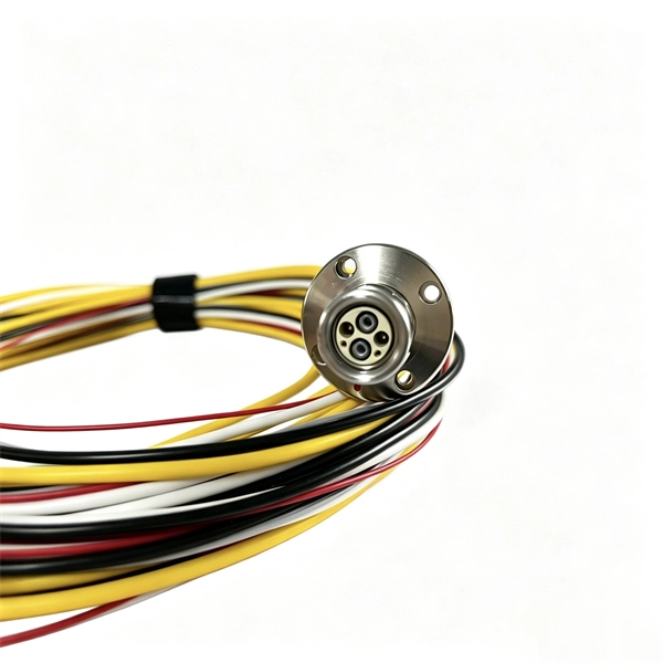
How many polarization states can be transmitted in polarization-maintaining fiber
Polarization-maintaining fibers work by intentionally introducing a systematic linear birefringence in the fiber, so that there are two well defined polarization modes which propagate along the fiber with very distinct phase velocities. In fiber optics, polarization-maintaining optical fiber (PMF or PM fiber) is a single-mode optical fiber in which linearly polarized light, if properly launched into the fiber, maintains a linear polarization during propagation, exiting the fiber in a specific linear polarization state; there is. Polarization-maintaining fiber cables ideally maintain the linear polarization state of light (linear SOP) that is coupled into the fiber. Such fibers are thus high-birefringence fibers (HIBI fibers). There are essentially two common ways for doing that: A fiber can. In this article, the latest in FOC's series covering specialty fibers and their fabrication, we discuss polarization-maintaining (PM) fibers and the various approaches used to make them. Based on wave theory, this chapter will discuss the transmission and.
[PDF Version]
-
Should the cable management rack be installed in the front or the back
Leave space for cable management —especially in the back. Ensure front-to-back airflow by leaving gaps or using filler panels. This method helps maintain neatness and accessibility within the rack while ensuring efficient airflow and ease of maintenance. Both overhead and under floor pathways should be designed to support the weight of cables in the initial installation and it should also facilitate the addition of future cables. With proper design and structured tools, it helps organize cables, ensure stable signal transmission, simplify maintenance, and improve overall system. Here are some best practices for rack placement: Implementing hot and cold aisle containment is a fundamental strategy for improving airflow and cooling efficiency. The racks should be positioned in a way that optimizes.
-
Spacing of the side of the distribution box
Side clearance: There should be a minimum of 30 inches of clearance from the sides of all electrical equipment, but in no case less than the width of the equipment itself. This is referred to as the side-to-side working space. In industrial power distribution systems, cable distribution boxes (also known as power distributor boxes, distribution electrical boxes, or electrical power distribution boxes) are the core hub of power transmission, branching, and protection. Its layout directly affects the efficiency of the. NEC Article 314 establishes requirements for the installation and use of electrical boxes, conduit bodies, fittings, and handhole enclosures. NEC Article 408. Boxes distribute low currents in an area equipped with 1 to 12 RJ 45 sockets. They centralise connections to ensure flexibility and that the installation is up to date.
[PDF Version]
-
Three operating states of relay protection
Several operating coils can be used to provide "bias" to the relay, allowing the sensitivity of response in one circuit to be controlled by another. Various combinations of "operate torque" and "restraint torque" can be produced in the relay.OverviewIn, a protective relay is a device designed to trip a when a is detected. The first protective relays were electromagnetic devices, relying on coils operating on moving par. Electromechanical protective relays operate by either, or. Unlike switching type electromechanical with fixed and usually ill-defined operating voltage thresholds. Electromechanical relays can be classified into several different types as follows: "Armature"-type relays have a pivoted lever supported on a hinge or knife-edge pivot, which carries a moving contact. These relays may.