-
Electrical diagram of main distribution box
This AutoCAD DWG file provides a complete Electrical Single Line Diagram (SLD) of the MSB, along with a detailed panel layout, including circuit breakers, busbars, instruments, and feeders. Understanding the wiring diagram of the main electrical panel is crucial for anyone who wants to have a basic understanding of how electrical systems work. To understand how a breaker box works, it is helpful to. Power distribution panel is used for utilization of equipment. Power supply is received from LT panel and distributed to the outgoing feeders for utilization.
-

Wiring of a Simple Distribution Box in a Factory
Practice good wiring: secure grounding, neat cable management, proper insulation, and correct wire gauge and breaker size. Include protection devices like breakers, fuses, and surge protectors—each circuit should have its own protection. Comply with standards: Follow NEC, IEC . Learn how to wire a distribution box step by step! This video shows real on-site footage of electrical installation, demonstrating safe and standardized wiring methods used by professionals. Single-phase distribution boards are mostly used in domestic house wirings such as houses offices, shops, etc. If it's done poorly, you risk short circuits, fire hazards, or system failure. Done right, it ensures safety, compliance, and long-lasting performance. To ensure safety, efficiency, and meet the increasing demand for usage, the electrical distribution system needs to meet the following. Connection method: Each switch takes a wire from the incoming point and connects it to the incoming end of the switch, or uses parallel connection to reduce the difficulty of wiring. This is important to properly install it.
[PDF Version]
-
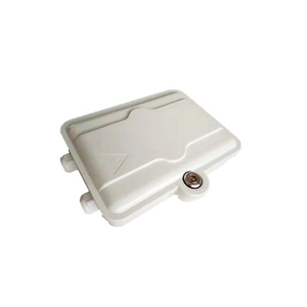
What issues should be considered when wiring the distribution box
Learn to identify & prevent power distribution cabinet installation problems like wiring errors, poor grounding, and safety risks to ensure building electrical system safety. It's always smarter to choose a box that's slightly larger than you think you'll need. A good box should have rust-proof coatings, especially for outdoor or humid. A cable distribution box is an electrical device used to collect, distribute, and protect electrical power. It is usually equipped with circuit breakers, fuses, terminal connectors, and other components. These can range from minor details to major safety defects. If your inspection report contains some of these, don't be alarmed; we are very picky, and many of the issues addressed here are common practice, if. Wiring Direction: Wiring between the main circuit breaker and each branch circuit breaker in the box generally goes on the left, and the wiring out of the distribution box generally goes on the right. Binding Requirements: The wires should be bound with plastic ties.
[PDF Version]
-
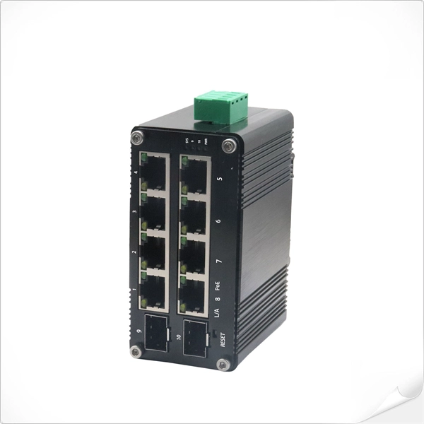
What lights on the router s fiber optic cable should be on normally
Green or white lights typically indicate normal operation. Understanding LED Indicators on a Fiber Router Let's break down what the common LED lights on a fiber router mean and how they behave: 1. POWER Normal: Solid/stagnant light. If OFF: The router is not powered — check the socket, adapter, or power cable. PON (Passive Optical Network) Normal: Solid. Whether your modem is blinking orange, your router has a solid red light, or you are staring at a mysterious "DS" indicator, you will find the answer below. If you're using a power strip, check. These lights act as a quick diagnostic language shared by routers, modems, and gateways, helping both users and technicians instantly identify issues such as signal loss, authentication failures, or network traffic. While colors and patterns vary by manufacturer, the underlying logic is.
[PDF Version]
-
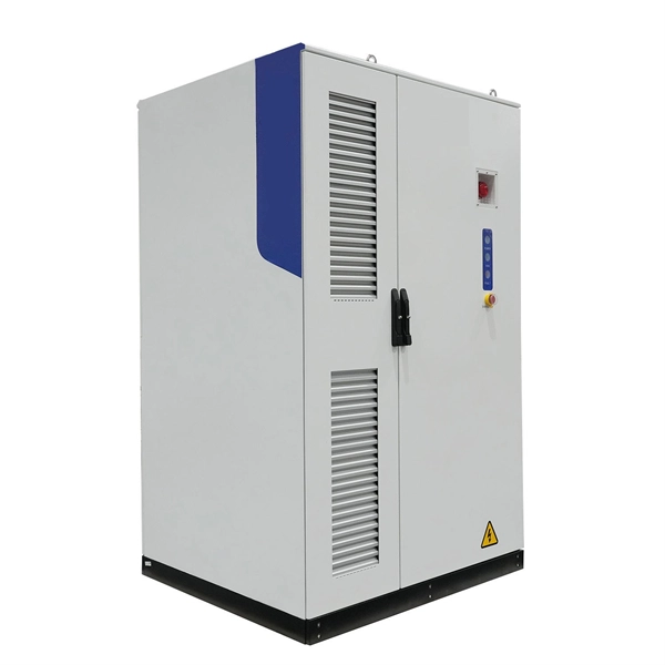
Emergency stop device added to secondary distribution box
The emergency breaking device can be located remotely in the secondary distribution board which supplies all the local circuits, as long as it is easily accessible, identifiable and installed in a location.
-
The eye diagram of the optical module is very poor
The key parameters used to judge whether an eye diagram is normal include eye height, eye width, jitter, and extinction ratio. For beginners, this might sound confusing—but don't worry. You will also get practical selection criteria, common failure modes, and a head-to-head decision matrix for choosing test setups. The eye diagram test is an indispensable methodology for evaluating the signal integrity and performance of high-speed digital communication systems, particularly in the domain of optical transceivers. The diagram is generated by overlaying multiple traces of a signal on an oscilloscope.
-

Relay Protection Circuit Diagram Numbering Rules
This handbook covers the code of practice in protection circuitry including standard lead and device numbers, mode of connections at terminal strips, colour codes in multicore cables, dos and donts in execution. Also principles of various protective relays and schemes including special protection. For power grid systems, ANSI and IEEE functional number codes dictate the use and restrictions of both the devices themselves, as well as the functions of those devices within the scope of a circuit. These devices include switches, disconnects, circuit breakers, generators, and motors. One is given in ANSI Standard and uses a numbering system for various functions. The functions are supplemented by letters where amplification of the function is required.
-
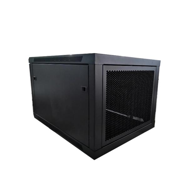
Data Center Power Distribution Box Wiring Costs
Key drivers include project scope, load requirements, conduit routing, and local permit fees. Continue reading as we delve into the various cost factors influencing electrical wiring installation and rewiring projects in data centers, providing insights to help you anticipate potential expenses for this critical infrastructure enhancement. Whether it's an office buildout or a warehouse renovation, this calculator provides a good starting point for planning. Buyers typically pay for materials, labor, and permits, with the main cost drivers being project complexity, building size, and local labor rates. The design is based on the customer deploying IT equipment with redundant power supplies sometimes referred to as dual corded loads.
-
Cable tray internal wiring installation
Proper planning for installing cable tray includes calculations based on loading, support systems, cable/wire fill and spacing, conductor types, securing of the cables and wire, and proper grounding and bonding are all important aspects of cable tray installation. NEMA VE2 addresses cable tray installation and provides information on maintenance and system modification. The following pages address the 2014 National Electrical Code® requirements for cable tray systems as well as design solutions from practical experience. headquartered manufacturer with over 130 years of supplying solutions for the electrical and data markets. Hubbell's strength is demonstrated by a long-standing reputation for supplying reliable. en completely installed, without damage either to conductors or structural system use maintain spacing or to keep cables in place when the tray is ect the minimum bend ra-dius for cables as they exit the bottom of the cable tray. A rung spacing of 6 to 9 inches (150 to 230 mm) is preferable when. How about organizing your wiring with a cable tray system? Smart move.
[PDF Version]
-

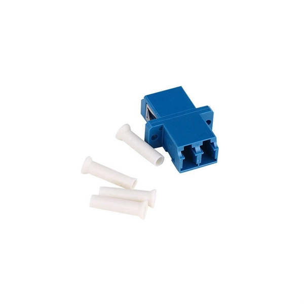
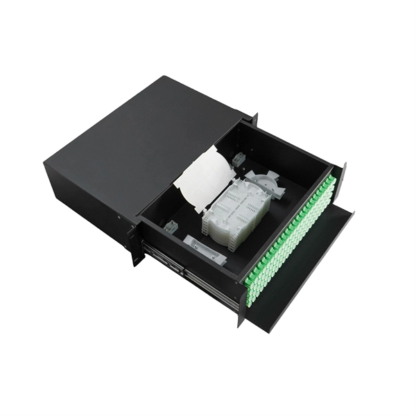
Fiber optic cable wiring color sequence and price
This guide explains the latest EIA/TIA-598-D fiber color-coding standard used to identify fiber types, inner fiber sequences, and connector polish styles. With clear tables and updated details, it serves as a comprehensive reference for technicians handling modern fiber optic. By adopting the TIA/EIA‑598C standard, you gain a universal “language” of colors that speeds identification, reduces miswiring, and enhances safety across cable jackets, connectors, buffer tubes, and splice trays. Fiber optic color codes provide the essential identification framework that enables fiber technicians and network professionals to manage complex optical network installations efficiently. Tubes with 24 uniquely colored fibers: Fibers 1 to 12 use the standard blue through aqua color sequence. Critical Exception: Outdoor cables are almost always black (for UV resistance), regardless of the fiber inside.
[PDF Version]
-

Is wiring a distribution box easy
This system has two main wires: one “hot” wire and one neutral wire. It is perfect for lights, TVs, and small appliances. Learn how to wire a distribution box step by step! This video shows real on-site footage of electrical installation, demonstrating safe and standardized wiring methods used by professionals. Whether you're a professional or a DIY enthusiast, understanding the correct procedure can prevent accidents and ensure optimal performance.