-
Cable tray standard drawing
Download a comprehensive set of Cable Tray Installation CAD Blocks in DWG format, ideal for electrical engineers, MEP designers, and industrial layout planners. Hubbell's NEXTFRAME® Ladder Tray is the effective and widely used cable runway that supports and delivers bundles of cable between cabinets, racks, and closets, along walls, and suspended from ceilings. The Ladder Tray features light, rugged, tubular steel construction. It is designed for. us-trations without notice. All illustrations, descriptions and technical information included in this document are provided as indications and can cable trays are equivalent. The mechanical and electrical characteristics, tests, certifications, overall quality management, recommendations mentioned. Our cable tray design considerations guide details key factors to consider when designing cable tray systems for industrial and commercial applications.
[PDF Version]
-
Standard Requirements for Busbar Connection Distance
The IEC standard for busbar clearance plays a critical role in the design and safety of electrical panels and power distribution systems. Key technical considerations include: 1. These clearances help prevent arcing, short circuits, and. Undersized busbar spacing is not a cosmetic defect. Dielectric tests, power frequency withstand for all voltages and impulse withstand for medium voltage, are specified in the standards. The design must pass these tests.
-
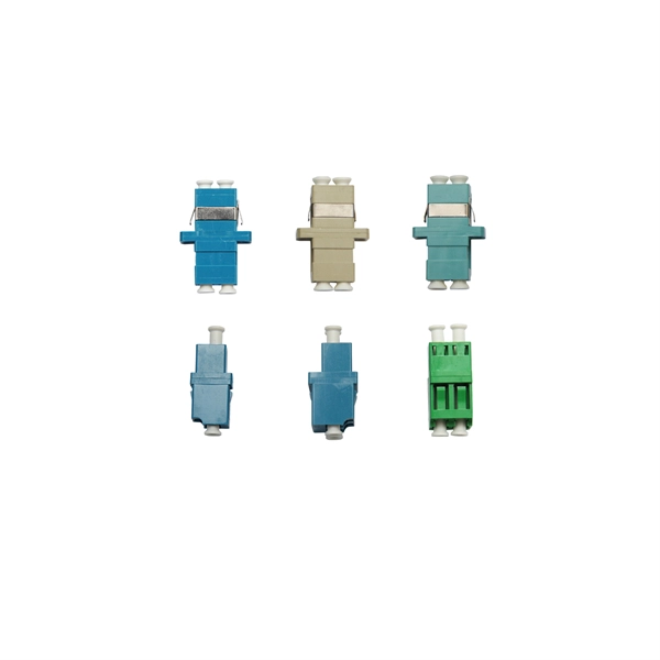
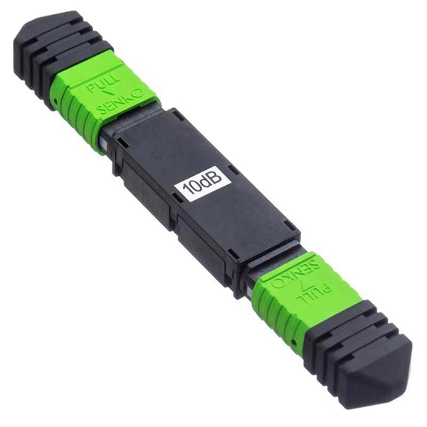
Fiber Optic Connector ST Inspection Standard
This standard covers the inspection of fiber optic connectors with a microscope and cleaning the connectors. Look for dirt, contamination, scratches or any other problem. adhesives for faster terminations. Single-mode and multimode connectors come with a 2-3 mm boot, a 900-micron boot, a dust cap, and a crimp ring. For optimal connectivity performance, invest in a Fiber Optic Inspection and Cleaning Kit for your installation team. The fibers shall terminate in 2. A full catalog of TIA specs is at org/ Learning More About Standards and Codes There are a number of ways of finding out more about cabling. Among these, SC (Subscriber Connector) and ST (Straight Tip) connectors stand out as widely recognized standards, conforming to the EIA/TIA 568A specification.
-
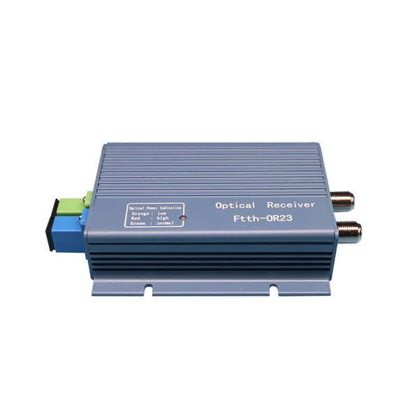
Fiber Optic Cable Duct Laying Price Standard
Fiber optic cable installation costs average $4,500 for most homeowners, with most installations ranging from $1,500 to $7,000. The main cost drivers include material type, run length, trenching or aerial work, and any required permits or inspections. With prices ranging from $1 to over $ 50 per linear foot, depending on the installation method. In the United States, customers typically pay for fibre optic installation per kilometer with separate line items for trenching, conduit, cable, and labor. This article provides cost. Cost of Laying Fiber Optic Cable in the U.
-
Standard for Depth of Molded Cable Trays
Depth — single-layer is ideal; multi-layer is allowed but demands derating and careful stacking rules. Fill ratio — IEC 61537 and NEC Article 392 both cap power cables at 40–50 % of the tray cross-section. In practice, cable tray dimensions are a system of interrelated measurements —width, depth, length, and material thickness—that directly affect cable fill compliance, heat dissipation, structural loading, and long-term expandability. From an engineering standpoint, cable tray dimensions are not. us-trations without notice. The selection of material and finish is a function of the environment in wh tant in a wide range.
-
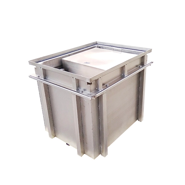
What s inside a standard secondary distribution box
An electrical sub panel, also known as a sub panel box or breaker box, is an essential component of an electrical system. Primary distribution systems consist of feeders that deliver power from distribution substations to distribution transformers. It ensures that electricity flows. secondary unit substation is a close-coupled assembly consisting of enclosed primary high voltage equipment, three-phase power transformers, and enclosed secondary low voltage equipment. The SDB can be fitted with terminal blocks for custom.
-

PV1F Optical Cable Standard
PV1-F is a tinned copper photovoltaic cable designed for DC connections in solar power systems. It complies with IEC 62930 and EN 50618 requirements, offering UV resistance and flame retardant performance. Suitable for fixed installations, internal and external, within conduit or systems, but not direct burial applications. In international PV projects, it is commonly referenced with PV Wire, USE-2 and UL 4703. PV1-F is configured for PV string wiring, combiner links, and inverter-side DC routing. It. Before diving into the process of choosing the right PV1-F cable specification, it's important to have a basic understanding of the PV1-F cable itself.
-
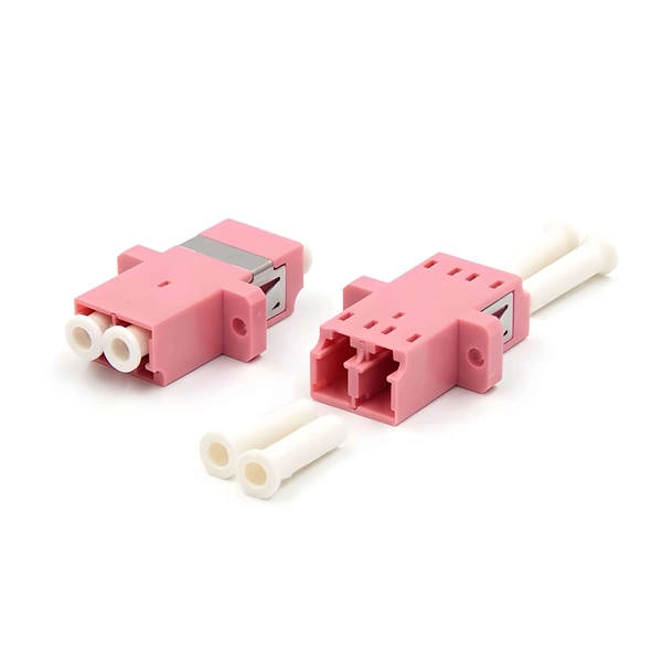
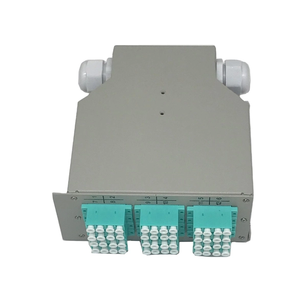
451 Standard Optical Cable Connector
Versatile as well as space-saving for ribbon cable applications, 3M™ Ribbon Cable Wiremount Socket 1. 050") Pitch 451 Series is a robust connector in a small package. It features a socket body in multiple positions, along with a cover and an optional strain relief. These compact, robust connectors with a fine pitch enable high. The 451 series socket assemblies and 452 series board-mount headers from 3M feature small packages for minimizing the PCB space and 30 µAu and Au flash plating versions for multiple mate and unmate cycle option levels at different price points. 025" PITCH MPATIBILITY: 3M. 050"), SERIES 452 HEADER WITH L HE EVENT OF CONFLICT BETWEEN THIS DATA AND THAT CONTAINED IN RE CE RELATED DOCUMENTS: PRODUCT SPECIFICATION: 3 DOC.
-
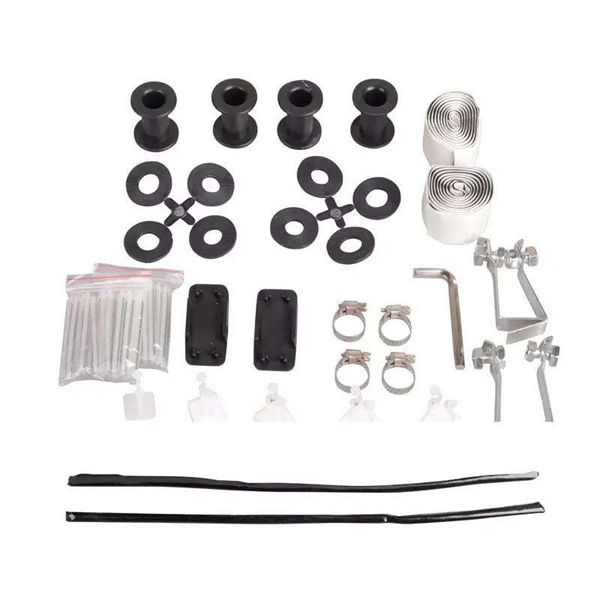
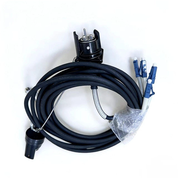
Standard for pigtail usage distance
Single-mode pigtails (OS2, 9/125 um) are used for long-distance telecommunications, FTTH deployments, and DWDM systems. They carry a single light path and support transmission distances of up to 100 km or more. Metal raceways, cable trays, cable armor, cable sheath, enclosures, frames, fittings, and other metal noncurrent-carrying parts that are to serve as grounding conductors, with or without the use of supplementary equipment grounding conductors, shall be effectively bonded where necessary to ensure. This changed in the 2023 code: 300. 14 Length of Free Conductors at Outlets, Junctions, and Switch Points. The pigtails can be any length you want. The requirement is for the conductors entering the box not the pigtails. Roger has posted. A pigtail in electrical wiring is a short wire used to connect multiple wires to a single point or device. It ensures a secure connection by combining wires with a wire connector, like a twist-on connector or a wire nut, and then linking them to the intended terminal or fixture.
[PDF Version]