-

Spectrum Analyzer Intensity
An optical spectrum analyzer uses reflective or refractive techniques to separate out the wavelengths of light. An electro-optical detector is used to measure the intensity of the light, which is then normally displayed on a screen in a similar manner to a radio- or audio-frequency spectrum analyzer. The input to an optical spectrum analyzer may be simply via an aperture in the instrument's case, an. OverviewA spectrum analyzer measures the magnitude of an input signal versus frequency within the full frequency range of the instrument. The primary use is to measure the power of the spectrum of known and. analysis was first used by in the late 1600s. In a letter to the, he described how he used an optical prism to separate white light into its constituent colors. Spectrum a. Spectrum analyzer types are distinguished by the methods used to obtain the spectrum of a signal. There are swept-tuned and fast Fourier transform (FFT) based spectrum analyzers: • A.
[PDF Version]
-
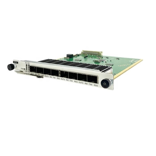
Principle of Fiber Optic Communication Spectrum Analyzer
These instruments are used to measure wavelength emissions from Lasers, Laser Diodes and LED's into the near infrared. From detecting signal distortions to optimizing optical. Optical spectrum analyzers are specialized instruments that measure light intensity as a function of wavelength. The COSA-4055 module offers the functionality and speed of an OSA in a handheld form factor at a fraction of. E/O converters use light-emitting elements such as semiconductor lasers, O/E converters use light-receiving elements such as photodiodes, and optical elements such as lenses are used at the input and output of optical fiber.
-
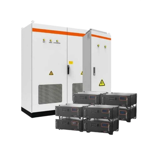
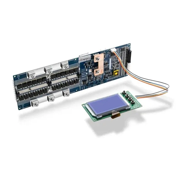
Key Points for Relay Protection Operation
Relay protection is the discipline of designing schemes that detect faults, coordinate relays, and isolate equipment without outages. While this is bad, It's not a. The potential transformers (PTs) and current transformers (CTs) usually produce electrical signals which monitor the state of current and voltage in a system. CTs and PTs reduce the high currents and voltages of a power system to those levels which can be handled by a relay safely. It emphasizes selectivity, coordination, fault response, and system behavior rather than individual relay devices.
-
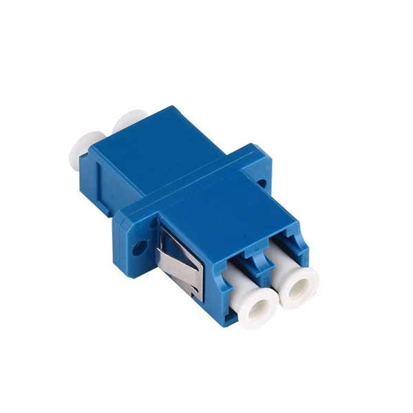
Optical Cable Positioning and Injection Method Operation
In fiber optic cable blowing, high-speed airflow is combined with a mechanical pushing force to produce the installation, known as blowing or jetting. This is the preferred method for pushing fiber optic cable thr.
-
Power Grid Optical Cable Operation Level
Key OPGW testing methods include visual inspection, OTDR testing, optical power meter testing, continuity tests, and various mechanical and environmental tests. Each method targets a specific aspect of cable performance and safety. OPGW stands for Optical Ground Wire. These cables are used on high voltage power lines. I have managed many projects where I personally oversaw the testing process. I know that if testing. This specification defines the design, material, performance and test requirements for fibre optic cable to support the fibre optic telecommunication needs. How to calculate the required fault. ion infrastructure. Optical Ground Wire (OPGW)/Underground Fiber Optic Cable (UGFO) plays a crucial role in ensuring seamless data exchange, real-time monitoring, and reliable operati n of power systems. However, with increasing demands and multiple stakeholders involved in fiber usage, it became.
[PDF Version]
-
Percentage of Spectrometer Analyzer
The fraction of light absorbed is the absorbance, A, and the percent of light not absorbed is the percent transmittance, %T. The absorbance and transmittance are characteristics of a sample and allow for iden.