-
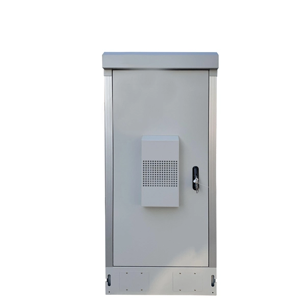
The Role of UPS Power Supplies in Industrial Control Systems
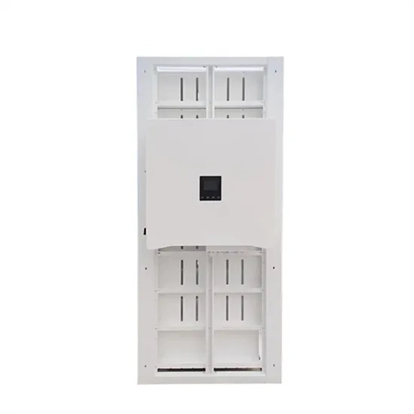
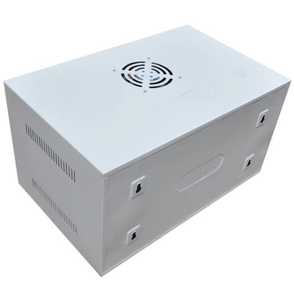
The Role of Industrial Grade UPS Systems Industrial grade UPS systems are designed to provide a continuous and stable power supply to manufacturing equipment, ensuring that operations can continue uninterrupted even in the event of a power outage or electrical disturbance. A control panel contains specific control devices in an automated system such as PLCs, HMI's, motion drives, safety sensors, network switches, among many others. Even with decentralized systems, the power source for the embedded control hardware comes from the main panel. Unlike standard UPS systems, industrial-grade units are built to. Drawing from Delta Wye Electric's 45+ years of experience installing and maintaining industrial UPS systems across manufacturing, pharmaceuticals, and critical infrastructure, this guide provides the technical insights facility managers and engineers need to make informed decisions. For facilities seeking a proven solution, the GTL33 Low Frequency Online UPS series (10–600kVA).
[PDF Version]
-
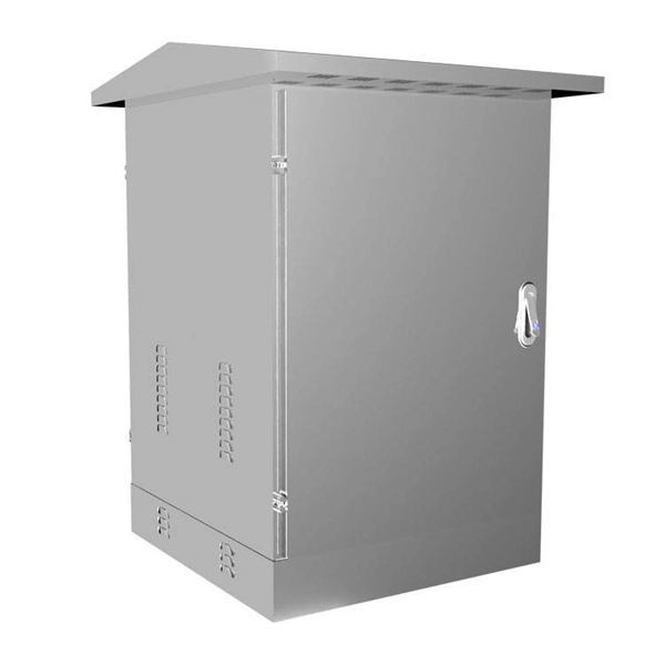
The Role and Importance of Communication Power Systems
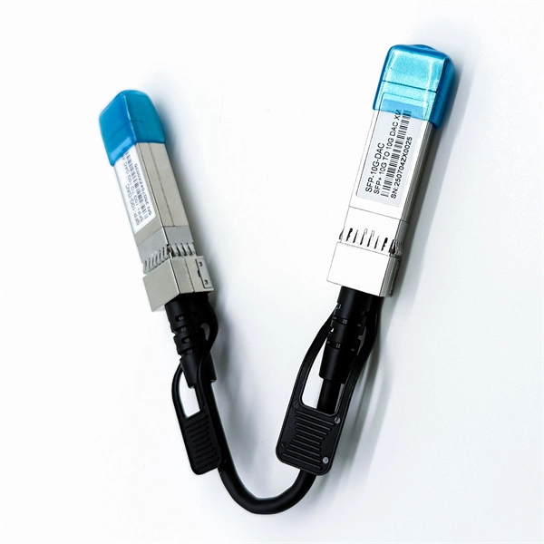
Power system communication networks play a critical role in the operation and management of modern electricity grids. These networks serve as the backbone for the seamless exchange of data between various components of power systems, including generation plants, substations, and. There are a several types of communication media such as micro wave, radio system, fiber optic, etc. Power system management functions are primarily divided into three interrelated areas: There are 3 distinct types of telecommunication networks. 2) Various communication schemes used including power line carrier communication, fiber optic communication, satellite communication and. The large-scale integration of converter-interfaced resources leads to the power grid transfor-mation from voltage-source-dominated to voltage-current-source-composite, which also raises new challenges to model and analyze the system synchronization.
[PDF Version]
-
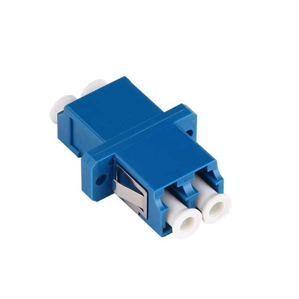
Light collection power of the second-stage beam splitter
It is currently used in modern three-CCD cameras. An optically similar system is used in reverse as a beam-combiner in three- LCD projectors, in which light from three separate monochrome LCD displays is combined into a single full-color image for projection.OverviewA beam splitter or beamsplitter is an that splits a beam of into a transmitted and a reflected beam. It is a crucial part of many optical experimental and measurement systems, such as In its most common form, a cube, a beam splitter is made from two triangular glass which are glued together at their base using polyester,, or urethane-based adhesives. (Before these synthetic,. Beam splitters are sometimes used to recombine beams of light, as in a. In this case there are two incoming beams, and potentially two outgoing beams. But the amplitudes.
-
How to pull up a power fiber optic cable
Fiber optic cables should always be pulled by the strengthened yarn fibers inside the outer jacket. This article explores recommendations for pulling and installing fiber optic cable. Most fiber optic cables boast a pull strength of 100 – 200. Fiber optic cable is surprisingly strong, durable and pliable; however, several best practices should be followed to ensure a successful cable installation. Most fiber damage does not come from normal operation after the system is live. More than half of cable problems happen because of wrong pulling. In 2025, new tools like hydraulic blowers, smart monitors, and better grips help you lower risks, save money, and keep the. A duct is available from point A to point B, a pull tape is blown in, a fiber optic cable is attached to it and the cable is pulled through the duct.
-

Can PoE power be turned off on a PoE switch
For TP-Link PoE switches, except for Unmanaged Switches, we can disable/enable PoE power on individual ports under PoE > PoE config, and PoE Status of PoE port is enabled by default settings. 08-27-2024 07:21 AM Just so we are confusing folks - We don't turn off switch port just to turn off PoE. To disable PoE only for an interface, go. Please note that the TL-SG108 doesn't support PoE at all. If a device does not need PoE the switch/UDM will not supply any power on that port. In the Network Operations app, select one of.
-
Power Grid Optical Cable Operation Level
Key OPGW testing methods include visual inspection, OTDR testing, optical power meter testing, continuity tests, and various mechanical and environmental tests. Each method targets a specific aspect of cable performance and safety. OPGW stands for Optical Ground Wire. These cables are used on high voltage power lines. I have managed many projects where I personally oversaw the testing process. I know that if testing. This specification defines the design, material, performance and test requirements for fibre optic cable to support the fibre optic telecommunication needs. How to calculate the required fault. ion infrastructure. Optical Ground Wire (OPGW)/Underground Fiber Optic Cable (UGFO) plays a crucial role in ensuring seamless data exchange, real-time monitoring, and reliable operati n of power systems. However, with increasing demands and multiple stakeholders involved in fiber usage, it became.
[PDF Version]
-
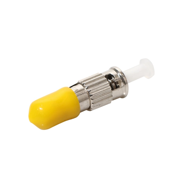
How to determine light attenuation of red light using an optical power meter
Optical attenuation compares input and output power on a logarithmic scale. When powers are in linear units, the loss in decibels is: Attenuation (dB) = 10 × log10 (Pin / Pout) If the link length L is provided, the attenuation coefficient is: Coefficient (dB/km) =. Analyze optical power drop across fibers and links. Switch units, lengths, and calculation modes easily. Needed when attenuation is an. Optical power, required for measuring source power, receiver power and, when used with a test source, loss or attenuation, is the most important parameter and is required for almost every fiber optic test. Backscatter and wavelength measurements are the next most important and bandwidth or. Optical power meters are a key element in the optimization and maintenance of such optical networks and of their components. But, for designers, just starting to work in the fiber-optic design space, measuring attenuation can seem like a monumental task.
[PDF Version]
-
Increase the light output power of the optical module
An optical amplifier is a device which receives some input signal light and generates an output signal with higher optical power. Typically, inputs and outputs are laser beams (very rarely other types of light beams), either propagating as Gaussian beams in free space or in a fiber. At the receiver end, the optical signals are reconverted into electrical. In this guide, we will explain what optical signal strength is, how to check it on Cisco IOS using the command line, and how to troubleshoot common light level issues. Assume the. This application note gives a short introduction to optical modules and the need of an optimized power tree in them and then concentrates on the use cases and benefits of four-switch and inverting buck-boost converters inside optical modules.