-

Normal transmit and receive power of optical module
Transmit power is typically good when it is in the 6 dB range between -1 and -7 dBm. This guide provides average transmit and receive power ranges for transceiver modules. The TX (transmit) and RX (receive) power levels significantly affect everything from signal strength to transmission distances and the overall optical power. For network engineers working with fiber optics (SFP, SFP+, QSFP), understanding TX (Transmit) and RX (Receive) signal strength is critical.
-
What s causing the optical module to have no light
Tip #5: How to deal with a “no light” issue? There are several reasons for “no light” issues: incompatible SFP module, incorrect connection, SFP module not powered on, or bad SFP. Incompatible SFP: Please check the compatibility of your optical transceiver with your. Tip #2: Why the LED of the switch slot does not light up after inserting the transceiver? It may cause by two reasons: compatibility issues and physical connection issues. If you have not inserted the SFP/SFP+/ XFP transceiver module into the switch slot correctly, it or link loss. The first thing. An optical module is a critical component in modern optical communication systems, directly affecting transmission stability, network reliability, and operational efficiency. However, during installation and daily operation, various issues may arise.
-
APM Optical Flow Module Debugging
Cut and resolder the MISOLVL jumper on the back of the board to switch the MISO pin to work on 3. If the sensor is mounted to a stabilized gimbal or mount, set FLOW_OPTIONS bit 1 to “1”. To know more about our new products, please visit www. com, we will serve you wh eed for GPS. This is critical to ensure the optical flow sensor does not interfere with APM is a open source flight control system, it is a multifunction system that can support quadrocopter, as well as aircrafts of fixed -wing, three-axis, 6-axis,8 –axis etc. APM flight control is a rather mature technique with formidable capabilities: it supports GPS designated cruise and automatic. Instead please use the PX4Flow sensor. The PX4FLOW is not yet supported in Plane or Rover. These are camera modules that use ground texture and visible features to determine aircraft ground velocity.
[PDF Version]
-
What are the components of an optical guide driver module
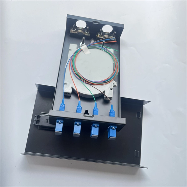
The optical module is usually composed of Transmitter Optical Subassembly (TOSA, containing a laser LD Chip), Receiver Optical Subassembly (ROSA, containing a photodetector PD Chip), a driving circuit, and an optical and electrical interface. Its schematic is shown in Figure 1. The internal structure of an optical module is complex but can be divided into several main parts. It is the core device for connecting communication equipment with optical fibers. Operating at the physical layer of the OSI model, optical modules are core devices in optical. As an important part of fiber-optic communication, an optical module is a photoelectric converter which converts electrical signals into optical signals and vice versa. Composition of Optical Modules The optical module, known as Optical Transceiver in. The optical module serves as a crucial component in optical fiber communication systems, operating at the physical layer, which is the lowest layer in the OSI model.
[PDF Version]
-
How does the optical module test group perform its tests
Optical modules will go through strict testing and quality inspection procedures before shipment, such as material testing, parameter testing, aging testing, real machine testing, end-face testing, etc. In fiber optic networks, optical transceivers such as SFP, SFP+, QSFP28, and QSFP-DD play a vital role in converting electrical signals into optical signals and vice versa. Testing these modules ensures performance, compatibility, and long-term reliability in bandwidth-intensive environments like. QSFPTEK suppliers have strict transceiver testing and quality control processes, and each optical module is delivered with a complete testing process. Optical modules can realize end-to-end signal transmission, and it performs optical communication through optical fibers. However, due to the architectural differences between 4-channel and.
[PDF Version]
-
Does the optical splitter need an optical module and how is it connected
The optical transceiver module (like an SFP, SFP+, or XFP module) in the OLT is the laser source that generates the initial light signal. This high-power signal is transmitted down the single fiber. When it reaches the optical splitter, the signal is divided and sent. A fiber optic splitter is a passive optical component that divides a single incoming optical signal into two or more outgoing signals, or combines multiple incoming signals into one. Conversely, it can also combine multiple signals into one. It is a passive optical device with many input and output terminals, especially applicable to. An Optical Splitter (also known as a fiber optic splitter or beam splitter) is a passive optical power management device.
-
Is the R-port on the optical module for receiving or transmitting light
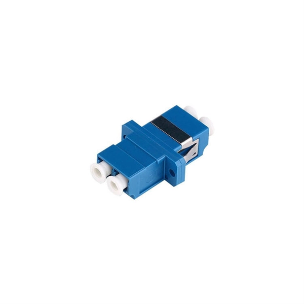
ROSA is the component inside the receiver side of the SFP port. The ROSA is responsible for receiving the optical signal transmitted by the TOSA of the opposite end's transceiver and converting it back to an electrical signal so that the communication equipment can understand it. Optical modules typically have an electrical interface on the side that connects to the inside of the system and an optical interface on the side that connects to the outside. The integrated optical transceiver module is the core device of optical communication, which completes the optical-electrical/electrical-optical conversion of optical signals. We'll cover everything from physical form factors to spectral characteristics, modulation formats. Ensures a proper connection between the optical module and the optical port of the device. It exists only on an SFP optical module.
[PDF Version]
-
Does the optical port include a module
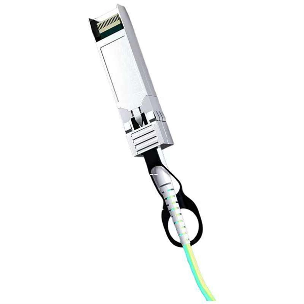
An optical port is a physical interface used to connect fiber optic cables. Currently, mainstream optical modules include SFP and QSFP form factors, with transmission rates ranging from 2M to 100G. Unlike fixed RJ45 copper ports, SFP ports support both fiber and copper modules, enabling far longer distances, greater flexibility, and improved scalability in enterprise. An electrical port module, also known as an optical-to-electrical port converter module, is a hot-swappable device with an SFP form factor. In addition, because the transmission distance of electrical port. The optical module serves as a crucial component in optical fiber communication systems, operating at the physical layer, which is the lowest layer in the OSI model. Its primary function is to achieve optoelectronic conversion by converting electrical signals into optical signals and vice versa.
[PDF Version]
-
What is an optical module and its application scenarios
An optical module is a small device that moves data using light. It changes electrical signals into light signals and back again. This helps data travel faster and farther than with copper cables. Optical modules are very important for fast internet, cloud computing, and other. When it comes to optical modules, I'm sure everyone is quite familiar with them. Optical modules typically have an electrical interface on the side that connects to the inside of the system and an optical interface on the side that connects to the outside. As an essential component of optical fiber communication, optical modules are optoelectronic devices that facilitate the conversion between optical and electrical signals during the transmission process. An. Aerech Networks will use this article to introduce you to the application scenarios of optical modules.
[PDF Version]
-
Installation of Optical Flow Positioning Module
Step1 : Connect the MTF-01 to PC by using the USB to TTL module. Step3: Open the MicoAssistant software, select the correct COM in the upper right corner, baudrate should be 115200, and then. Optical Flow uses a downward facing camera and a downward facing distance sensor for velocity estimation. It can be used to determine speed when navigating without GNSS — in buildings, underground, or in any other GNSS-denied environment. Instead of relying on GPS, this sensor tracks visual features on the surface beneath the drone and reports how those features move between frames. With the right. Flying an FPV drone in Position Hold and Altitude Hold modes can be significantly improved with the addition of Optical Flow and Sonar (rangefinder) sensors.