-
Schematic diagram of trough-type cable tray
Legrand continues to be an innovator in cable management solutions and is proud to introduce Cablofil Trough Tray, a cable management system designed to maximize network reliability and minimize lifec.
-
Relay protection refers to the occurrence of
Relay protection is the discipline of designing schemes that detect faults, coordinate relays, and isolate equipment without outages. It functions as a watchdog by constantly surveying multiple system components including voltage, current, frequency, and phase angle. It emphasizes selectivity, coordination, fault response, and system behavior rather than individual relay devices. : 4 The first protective relays were electromagnetic devices, relying on coils operating on moving parts to provide detection of abnormal operating conditions such as. Operational Continuity: Restricts outages to affected areas, keeping the rest of the system online. How Does a Protective Relay Work? A protective relay operates by continuously monitoring electrical. Electromechanical Relays: Work using moving parts and electromagnetic forces (traditional relays). Numerical Relays: Digital relays that use microprocessors, offering advanced protection and monitoring features.
[PDF Version]
-
Relay protection positive negative and zero sequence
Relays use positive, negative, and zero sequence components to detect and isolate faults efficiently. Negative sequence components help prevent overheating and mechanical stress in rotating. Symmetrical components in power systems (positive, negative, and zero sequences) are indispensable tools for power system engineers dealing with unbalanced conditions in three-phase systems. This method, first introduced by Charles Fortescue, simplifies complex scenarios, enabling easier fault. Positive Sequence Impedance: Positive sequence impedance is the resistance faced by positive sequence current, crucial for calculating three-phase faults. We must practice these techniques in order to fully understand and feel comfortable with them.
-
Phenomena of relay protection failure
It occurs when the relay fails to adequately connect or disconnect its contacts in response to a fault or abnormal condition. This project investigated failure modes of control, timing, auxiliary, and protective relay models in service in U. Although the data utilized is from U. This theoretical side has its practical s on Hidden. Selectivity is a mandatory requirement for all protection, but the importance of it depends on the application. For example, unselective protection operation during a medium voltage network fault will cause an outage for an unnecessarily large number of consumers. However, like any electrical device, relays can experience failures that compromise their intended function.
-

Relay protection circuit protection
Distance relays, also known as impedance relay, differ in principle from other forms of protection in that their performance is not governed by the magnitude of the current or voltage in the protected circuit but rather on the ratio of these two quantities.OverviewIn, a protective relay is a device designed to trip a when a is detected. The first protective relays were electromagnetic devices, relying on coils operating on moving par. Electromechanical protective relays operate by either, or. Unlike switching type electromechanical with fixed and usually ill-defined operating voltage thresholds.
-
The Function of Optical Cable Communication Protection Pipes
PPR pipes, especially weld PPR pipe, provide unmatched protection for power and optical cable sheaths. Also required is an additional, protection against cable bundles. The hdpe silicone core pipe for fiber optic communication cable represents a revolutionary advancement in telecommunications infrastructure technology. This specialized protective conduit combines high-density polyethylene (HDPE) outer construction with an innovative silicone core design, creating. Introduce PPI as a resource of knowledge for HDPE conduit Present HDPE conduit products and explain their benefits Discuss the applications addressed by HDPE conduit solutions Illustrate several installation techniques used with HDPE conduit List industry standards used for HDPE conduit Share. e pipes, or for laying them directly into the ground. The most important types of these cables are OPGW (Optical Power Ground Wire), OPPC (Optical Phase Conductor), ADSS (All-Dielectric Self-Supporting) and SkyWrap. Size: 32/26, 34/28, 40/33,46/38, 50/41, 63/54 3. CO (Certificate of Origin): China, CO could be provided by free.
[PDF Version]
-
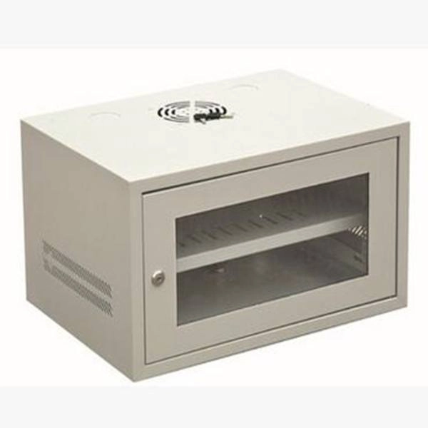
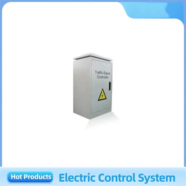
Standards for Setting Plant Auxiliary Relay Protection
This VuSpec includes 47 active IEEE standards, guides, recommended practices in the Power Systems Relays family. Purpose: To document and implement programs for the maintenance of all Protection Systems, Automatic Reclosing, and Sudden Pressure Relaying affecting the reliability of the Bulk Electric System (BES) so that they are kept in working order. 2. To set load-responsive protective relays associated with generation Facilities at a level to prevent unnecessary tripping of generators during a system disturbance for conditions that do not pose a risk of damage to the associated equipment. Generator. Relay systems protect high-voltage equipment and transmission lines to ensure safe, stable systems. This paper first reviews these.
-
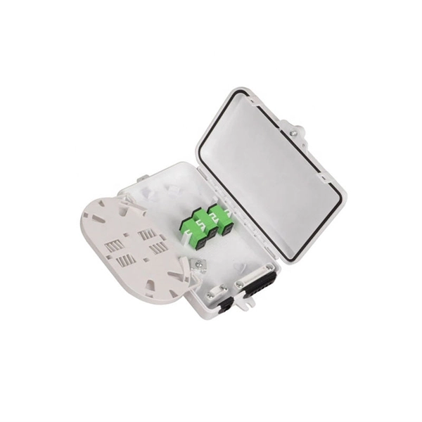
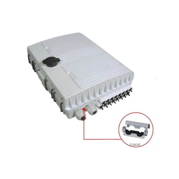
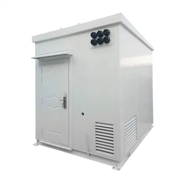
Lightning protection and grounding of mobile optical distribution boxes
This Recommendation provides guidance on protecting indoor distribution systems for mobile communication in large-scale buildings from lightning and safety risks. It emphasizes compliance with standards like IEC 62305-3, IEC 62305-4, IEC 60364 series, and ITU-T K. 21 for effective. We make safe, reliable and high-quality solutions for every spec and project. Lightning protection needs vary according to each specific facility. It is located at an elevation such that a line passing through the static wire and the outermost conductor below it is at a 30° aximum angle with a vertical line. ERICO® has complete telecommunications applications solutions to help protect the facility against electrical noise, lightning induced surges and transients caused by. Ground rods are the most common grounding electrode found on distribution circuits.
[PDF Version]