-
How far apart should the cable tray be placed with its fixed support
Support spacing for cable trays must align with the manufacturer's instructions, as outlined in NEC 392. Generally, standard trays require supports every 6 to 10 feet, while heavy-duty, long-span trays can handle distances of up to 20 feet between supports. The NEC has a requirement for ladder-type cable trays. This is a description of how to select, install, and support these metal or plastic frames, on which electrical wires are installed. You should consider it as a series of instructions that make the buildings resistant to. When installing two cable trays in parallel at the same height, the distance between them should be no less than 0. But it's also important to minimize.
-
Stress on cable trays
Material selection: Cable trays are typically made from steel, aluminium, or fibreglass. Choose materials that meet or exceed industry standards (e. Is your cable tray system optimized for safety, dependability, space and cost savings? Cable tray (or cable ladder) systems are a popular alternative to electrical conduit systems, as they have an outstanding record for dependable service, design flexibility and cost savings in commercial and. This appendix provides the design criteria for seismic Category I cable trays and their supports. Seismic Category II cable trays and their supports are also designed utilizing the design criteria of this appendix. The selection of material and finish is a function of the environment in wh tant in a wide range. Cable trays are an essential part of modern electrical and communication infrastructure, providing critical support for power cables and wiring systems. The concept of “Cables in Free Air” for power distribution and control cables has been adopted primarily for economic reasons. Ensuring the structural stability of these systems is paramount to prevent accidents, downtime, and economic losses.
[PDF Version]
-
Translate the cable tray by 45 degrees
To create a 45-degree bend, cut the side rails to remove a segment calculated by the formula (Tan (22. Google's service, offered free of charge, instantly translates words, phrases, and web pages between English and over 100 other languages. So basically from my middle line what size to mark either side to cut my lip away to create different angles. Calculate horizontal, vertical, or compound cable tray offsets based on bend angle, offset distance, and available installation space. Measure this distance along the straight tray. ADVANCED S PRODUCTS I ASP 45° inuous system as well as stand-alone elements. 5∘ cuts on two separate pieces of cable tray. The second piece's cut must be in the opposite direction. Easy step to make 45 degree offset cable tray/Pipe and Air duct Cable tray 90 Degree Bend ! Cable tray ( Hindi) Cable tray 22. Distance of 145 mm ×.
[PDF Version]
-
Cable tray connector installation price
Cable tray pricing depends on materials, coatings, size, supplier margins, and order quantity —plus hidden costs like shipping and installation. Cable tray installation cost per meter varies by specifications; GangLong Fiberglass offers kits for raised floor system and facility needs. This guide breaks down everything buyers need to know, from price trends to cost-saving tips. The average cable tray price per meter ranges from $2 to. A cable tray system is used to support insulated electrical cables used for power distribution, control, and communication. A 2026 Comparison vs. The majority of individuals will consider the cost of the components. That number matters, but it's rarely the one that decides whether a project stays within budget. The real cost shows up later, during installation, during upgrades, and during the first few years of operation.
[PDF Version]
-
Installation of galvanized plastic cable trays
This guide covers the critical steps, from selecting the right electrical cable tray and performing accurate cable fill calculations to managing a safe cable pull through and ensuring all bonding and grounding requirements are met. Are you looking for a cost-effective and durable solution for organizing and protecting your cables? Look no further than cable tray galvanized. But before you lay the first tray or clamp down a single cable, you need a solid plan. This guide breaks down the process step by step. The selection of material and finish is a function of the environment in wh tant in a wide range of environments, and easily formable (Appendices II and III). The process described here takes a systematic approach to ensuring that cable tray installations meet safety, reliability, and project-specific needs while following to. Method Statement installation of Cable Trays and Ladders - Planning Engineer FZE.
[PDF Version]
-
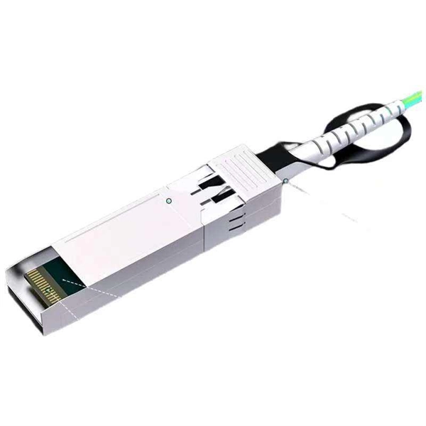
Qatar Optical Cable Silicon Core Tube Brand
Fibre Optic Cables and Accessories have taken the networking and telecom domain in their stride and offer one of the most popular and reliable means to communicate and share data. Electra is a leadin.
-
Requirements for installing cable trays on highways
Cable tray systems are recognized as a wiring method by many national and international electrical codes. Typical requirements address: Tray construction, load ratings, and materials. Support spacing, mechanical strength, and. Article Summary: A compliant cable tray installation requires a thorough understanding of NEC Article 392, proper structural support, and precise installation techniques. This guide covers the critical steps, from selecting the right electrical cable tray and performing accurate cable fill. This article explains the main requirements and good practices for cable tray systems, including tray types, materials, loading, supports, bonding, cable selection, and installation details.
-
The bottom plate of the trough-type cable tray has holes
A perforated cable tray—also called a ventilated trough tray —features a solid bottom with regularly spaced ventilation holes and continuous side rails. Some versions have small holes in the bottom. It is good for routing control cables and communication cables. From a structural. The ladder-type cable tray is designed with two long side rails that are connected by evenly spaced rungs, resembling a ladder.
-
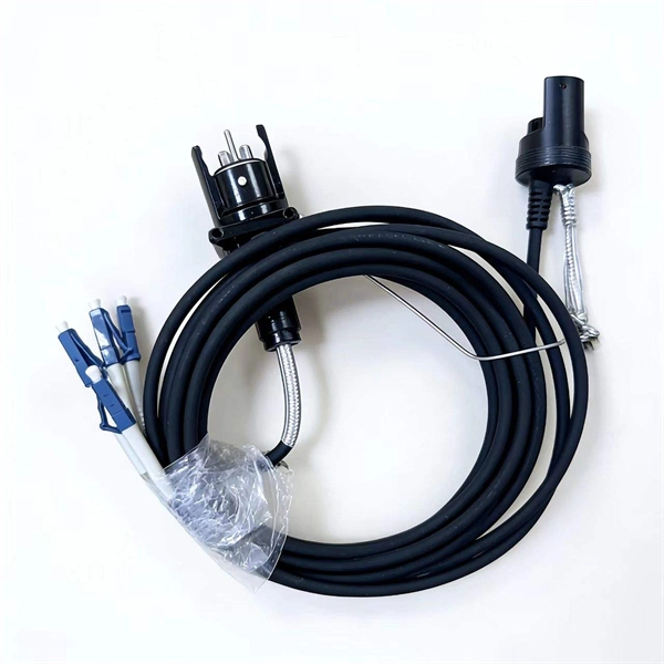
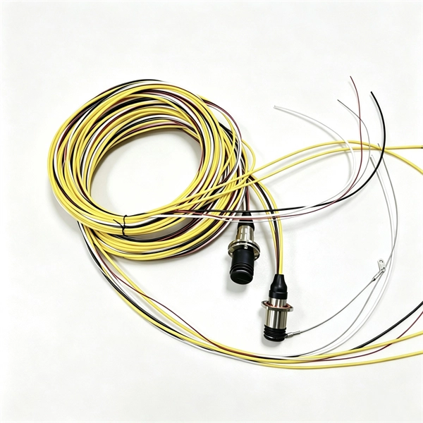
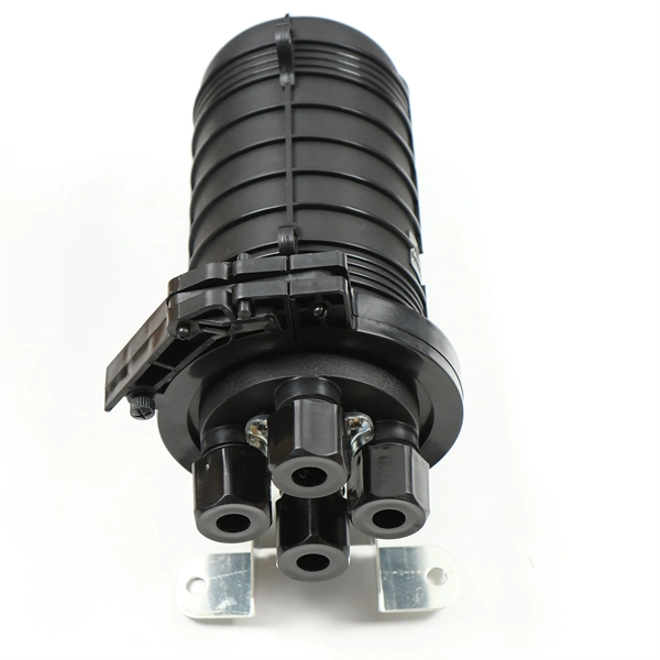
Fiber optic cable splice cannot be pulled out
This is often due to issues with connectors, splices, or faulty equipment. Use an OTDR to identify points of high return loss or reflection events along the link. Check the fiber's end-faces for imperfections and re-polish. A single imperfect splice can disrupt connectivity for businesses, schools, and homes, causing slow speeds, intermittent outages, and costly downtime. Whether it's from misalignment, dust contamination, environmental stress, or poor splice protection, these problems can quickly escalate if not. Successful splicing or termination relies on first being able to expose the fibers completely and safely. If the installer cannot do this, splicing or termination is irrelevant. This wikiHow article will teach you how to splice a cut fiber optic cable back together with a fiber optic stripper and cutter and a fiber optic crimper.
[PDF Version]