-
Relay Protection Control Program
NERC has developed Standard PRC-005, to ensure that all transmission and generation protection systems affecting the reliability of the BES are maintained and tested. June 15-19, 2026 This course provides foundational training in the areas of Protective Relays, Protection Schemes, Instrument Transformers, and other equipment used in Power System Protection and Controls. Laboratory exercises will cover proper relay maintenance, specific. Relay systems protect high-voltage equipment and transmission lines to ensure safe, stable systems. The course provides basic guidelines for relay application and settings calculation.
-
What is the relay protection time difference
The IEC standard for relay coordination recommends time grading between relays based on fault current magnitude and operating characteristics. For overcurrent protection, a minimum time margin of 0. 5 seconds is often maintained between primary and backup relays. The principle is to grade the operating times of the relays in such a way that the relay closest to the fault spot operates first. In order for the relay to operate, it needs to be energized. This energy can be provided by battery sets (mostly) or by the monitored circuit itself. In which case you use any of them. Are there any benefits of using one. A protection relay is a crucial component of electrical systems that safeguard infrastructure, employees, and equipment from electric problems and malfunctions. The relay settings that are selected are often a compromise in order to cope with both overload and. In electrical engineering, a protective relay is a relay device designed to trip a circuit breaker when a fault is detected.
[PDF Version]
-

Relay Protection Test Wiring Method
One approach to test the total protection system is to use primary injection techniques (see appendix H) that trigger protective relays and lockout relay, trip circuit breakers, and initiate annunciations and indications. If applicable, documentation is required detailing how verified protection segments overlap to ensure there is not a gap. The purpose of this Standard Work Practice (SWP) is to standardise and describe the method for testing of Ergon Energy protection relays for commissioning purposes. This SWP should be interpreted in conjunction with Standard for Substation Protection (V1. From a technician's perspective, master the unique skill of testing protection. When the transformer wiring type is Y/Y (Y0), the test wiring is very simple: when testing phase A, the tester IA is connected to the phase A of the high voltage side, and the tester IB is connected to the phase a of the low voltage side. After the neutral line of the high and low voltage sides is. Function: Use electronic components like transistors to perform switching. Applications: Frequency, undervoltage, and overcurrent protection.
[PDF Version]
-
Steps for Short Circuit Calculation in Relay Protection
Voltage levels, transformer ratings and impedances, line lengths and impedances, generator/motor data. Select fault location Choose busbars or nodes where faults will be studied. Apply IEC. A short circuit occurs when an unintended low-impedance path forms between: Physical Causes: Critical Applications: ⚠️ Safety Critical: Incorrect fault current calculations can result in explosive equipment failures, arc flash incidents causing severe burns, and system-wide cascading failures. The principle is to grade the operating times of the relays in such a way that. The scope of study involves calculating the settings for protective relays to achieve selectivity during faults ocurring in the electrical network for the 13. In OC relays the coordination is based on the relay time-current characteristics of instantaneous and/or time delay units. Instantaneous units should be set so they. As of this update, Service Disconnect Switches, Surge Protective Devices, Switchboards, Switchgear, and Panelboards, Industrial Control Panels, Motor Controllers, Elevators, Industrial Machinery, and Transfer Equipment are all required to have short-circuit current ratings.
[PDF Version]
-
Wiring of residual current circuit breaker in distribution box socket
In this video, I'll show you the complete wiring diagram of a home distribution board (DB). You'll learn how to connect the main circuit breaker (MCB), residual current device (RCD), and individual circuit breakers for lighting, sockets, and appliances. This guide provides a detailed, professional procedure for installing a Residual Current Circuit Breaker (RCCB)—a device essential for protecting people from the severe danger of electric shock. #dbbox #distribution #home #house. A distribution board or distribution box is where the main power supply is distributed to multiple loads. You will learn to build a safe, efficient, and professional electrical system today.
-

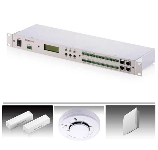
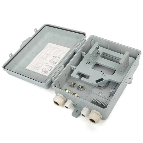
Two channels of relay protection for the network control building
The dominance of dual-setting directional overcurrent relays (DS-DOCRs) based protection schemes and associated high-reliability requirements require rigorous verification of these schemes before deployment.
-
Distribution box circuit breaker obstructed
Check the electrical load and ensure that the sensors do not exceed the 10 Amp maximum. In this guide, we'll walk through these. Issue: Frequent tripping of circuit breakers is one of the most common issues in distribution boards. It can occur due to overloaded circuits, short circuits, or ground faults. Using a light switch as a simple example, check each of the three wires.
-
Armenia Passive Optical Network Low Voltage Circuit
INCRIPT provides project development and management, turnkey solution implementation, installation, commissioning, and technical maintenance of low-voltage systems. The Relevance Inspector will open in the Coveo Administration Console. Our integrated circuits and reference designs help you create optical network terminal (ONT) units that enable high-speed data connections for today's passive optical networks. Use the resources below to design a system with our. INCRIPT emerges as a proficient systems integrator with over a decade of extensive experience in the Armenian market. Since its inception, the company has continuously evolved, refining its expertise in designing, building, and upgrading IT infrastructure and engineering systems. We offer turnkey. This paper presents the design and implementation of a passive optical network (PON) based on a gigabit-capable passive optical network (GPON) standard to deliver fiber-to-the-home (FTTH) services in a small-town setting. 5% of people in rural areas have access to the Internet, but only 73. The construction and deployment.
[PDF Version]
-
Serbian electrical cabinet wiring colors
BLACK: AC and DC main power chains; RED: AC control current chains; BLUE: DC control current chains; (dark blue) ORANGE: power chains that do not need to be separated according to 5. (wires that carry strange voltage and can remain live when the main switch of the cabinet . Colour identification by using common colours is permitted, provided that there is no risk of confusion and no GREEN or YELLOW is used, except in the two-colour combination GREEN-YELLOW. When using color codes for the identification of current conductors, it is recommended to use the following. ● Easy Identification: The colors immediately tell you the purpose of the wire. ● Simple Maintenance: Future repair or upgrade is easier and safer. ● Universal Standards: Enable electricians in various regions to learn about wiring systems within a short time. These codes help us to follow the safety rules. The colors and the labels can be observed below: From the list above we can conclude that: The UK now adapts IEC 60446 as its own wire color codes from British Standard BS.
[PDF Version]