-
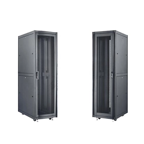
How many cascading levels does a fiber optic switch support
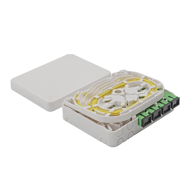
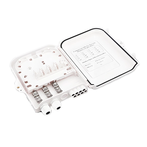
The switch connected to the switch is called cascade. However, in the actual application process, it is recommended that the cascade does not exceed four layers. Cascading can be defined as two or more switches. This guide focuses on two critical aspects of optical splitters that define FTTH performance: split ratios (how signals are divided) and splitting architectures (how splitters are deployed). A key challenge is determining how many users a single OLT port can support, which is defined by the split ratio. Traditional GPON networks often employ 1:32 or 1:64 splits. The connection between two or more Ethernet switches in a certain way (Uplink port, etc. Multiple switches can be cascaded in various ways according to. On the other side of the splitter, 32 fibers are routed through distribution panels, splice ports and/or access point connectors to 32 customers' homes, where it is connected to an optical network terminal (ONT).
[PDF Version]
-
How far is the wall support for a 200mm cable tray
The NEC requires that cable trays must be supported by members at an interval specified by the cable tray manufacturer, but not more than 5 feet for horizontal runs to support the weight of the cables and other loads. The NEC has a requirement for ladder-type cable trays. The National Electrical Code is a set of principles designed to promote public safety and welfare, as well as safeguard public health by regulating the design and operation of electrical facilities and. This is a description of how to select, install, and support these metal or plastic frames, on which electrical wires are installed. 1 Is it a. Cable Tray Support Span: The distance between supports is a critical calculation. Add Cables This calculator is provided for informational and educational purposes only. 1 Construction Manager is.
-
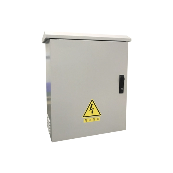
The distribution box track support fell off
Quality inspection: Make sure the distribution box and its components meet the standards, check whether the wiring is firm, and whether the materials are qualified. Qualified Builders: Hire an experienced electrician for installation and connections to avoid mistakes and omissions. Keep the inside of the box dry and clean. Surge protection devices help prevent damage from sudden spikes in voltage. Here is a quick checklist for your inspection: Common mistakes during. In modern power systems, distribution boxes are the core equipment for power distribution and control, and their stable operation is crucial to ensuring the safety and reliability of power supply.
-
How far apart should the cable tray be placed with its fixed support
Support spacing for cable trays must align with the manufacturer's instructions, as outlined in NEC 392. Generally, standard trays require supports every 6 to 10 feet, while heavy-duty, long-span trays can handle distances of up to 20 feet between supports. The NEC has a requirement for ladder-type cable trays. This is a description of how to select, install, and support these metal or plastic frames, on which electrical wires are installed. You should consider it as a series of instructions that make the buildings resistant to. When installing two cable trays in parallel at the same height, the distance between them should be no less than 0. But it's also important to minimize.
-
Elevator cable tray support spacing
Support spacing for cable trays must align with the manufacturer's instructions, as outlined in NEC 392. Generally, standard trays require supports every 6 to 10 feet, while heavy-duty, long-span trays can handle distances of up to 20 feet between supports. Specifiers should be aware that some cable tray. Understanding cable tray spacing is key to meeting safety regulations and maintaining system performance. The spacing between trays, whether horizontal or vertical, depends on various factors like cable type, environment, and tray material. The Ladder Tray features light, rugged, tubular steel construction. 50 in the development and approval of the document at the time it was developed.
-

How much distance should the cable tray support be installed
Generally, standard trays require supports every 6 to 10 feet, while heavy-duty, long-span trays can handle distances of up to 20 feet between supports. To determine the proper spacing, consult the manufacturer's load capacity chart, which accounts for the total weight of the. The NEC requires that cable trays must be supported by members at an interval specified by the cable tray manufacturer, but not more than 5 feet for horizontal runs to support the weight of the cables and other loads. The NEC has a requirement for ladder-type cable trays. This spacing is crucial for adequate maintenance access, ease of inspection, and ensuring proper airflow for effective heat dissipation. Support Methods: Common support methods include trapeze hangers, which are. This is a description of how to select, install, and support these metal or plastic frames, on which electrical wires are installed.
[PDF Version]
-
Experimental Report on Ceramic Fuse Pull-out Force Measurement
This paper identifies failure mechanisms of axial lead fuses subjected to real field ambient thermal profiles by finite element simulations and experimental testing. Experimental observation of failed fuses attribute.
-
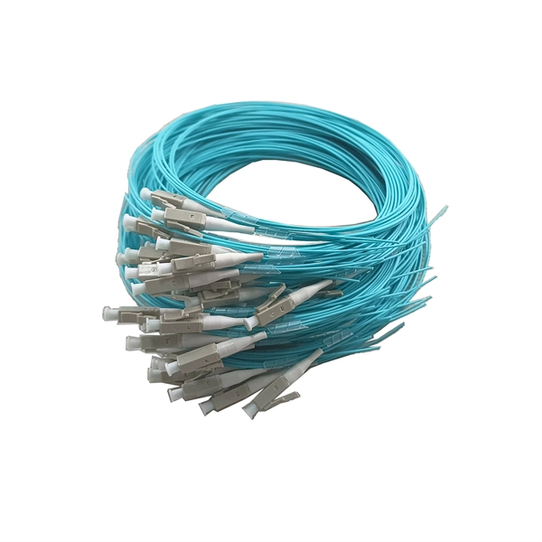
Fiber Optic Communication Industry Understanding Report
The fiber optics market is experiencing robust growth, propelled by the rising demand for high-speed communication networks, expanding internet penetration, and the rapid adoption of cloud servi.
-
1-meter wide cable tray support spacing
Generally, standard trays require supports every 6 to 10 feet, while heavy-duty, long-span trays can handle distances of up to 20 feet between supports. To determine the proper spacing, consult the manufacturer's load capacity chart, which accounts for the total weight of the. The NEC requires that cable trays must be supported by members at an interval specified by the cable tray manufacturer, but not more than 5 feet for horizontal runs to support the weight of the cables and other loads. The NEC has a requirement for ladder-type cable trays. The rungs cannot be more. en completely installed, without damage either to conductors or structural system use maintain spacing or to keep cables in place when the tray is ect the minimum bend ra-dius for cables as they exit the bottom of the cable tray. Proper installation can significantly reduce electromagnetic interference, prevent fire hazards, and improve overall efficiency. This article provides an in-depth. Ladder cable tray is available in widths of 6, 9, 12, 18, 24, 30, 36, 42 and 48 inches with rung spacings of 6, 9, 12 or 18 inches. The Ladder Tray features light, rugged, tubular steel construction.
[PDF Version]
-
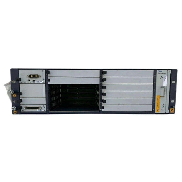
Does the C4506E support 100Mbps optical modules
The Cisco Catalyst 4500E Series 6-port 10 Gigabit Ethernet line card supports standard X2 optics as well as the Cisco TwinGig modules. Enabling security, mobility, application performance, video, and energy savings over your network infrastructure, the Cisco Catalyst 4500 Switch supports resiliency, virtualization, and automation, further improving the ease of network use. Cisco Catalyst 4500 Series Switches provide borderless. Provides information to identify and control this ST and its TOE. Lists acronyms and abbreviations used throughout the Security Target. Describes the TOE's architecture and its security-relevant features. The Supervisor 6L-E now supports full routing protocols, Open Shortest Path First (OSPF), Enhanced IGRP (EIGRP), Border Gateway Protocol (BGP), and many other.
-
Global Report on Fiber Optic Cables
This report is a detailed and comprehensive analysis for global Fiber Optics Cable market. Both quantitative and qualitative analyses are presented by company, by region & country, by Type and by Application. The fiber optics industry is projected to reach USD 6. 18 billion in 2024, at a CAGR of 16. The growth of market is attributed to factors such as proliferation of data centres and increasing deployment of 5G network. 21% during the forecast period from 2026 to 2035. I need the full data tables, segment breakdown, and. Global Outlook – By Fiber Material ( Glass Optical Fiber, Plastic Optical Fiber), By Product Type ( Single-mode Cable, Multi-mode Cable), By Application ( Telecom, Oil And Gas, Military And Aerospace, BFSI, Medical, Imaging, Railway, Other Applications) – Market Size, Trends, Strategies, and.
-
Test Report on a New Vertical Cavity Surface Emitting Laser
Recent results on highly reliable 940nm multi-junction high power vertical-cavity surface-emitting lasers (VCSELs) are presented with target applications in depth sensing and Light Detection Ranging (LiDAR) markets. Vertical-cavity surface-emitting lasers (VCSELs) having a small aperture and operating in a single transverse mode (SM) are known to reach high relaxation oscillation frequencies of 30-90GHz and, thus, can offer intrinsic modulation bandwidth beyond 100GHz, once photon damping and electric. In this work, we present a high-performance vertical cavity surface emitting laser (VCSEL) based on a single-crystal CsPbBr 3 microplatelet, fabricated through a simple solution process and sandwiched between two distributed Bragg reflector (DBRs). Our innovation, the antireflective.