-
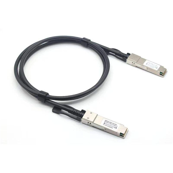
Selection Guide for 40G Tunable Optical Modules for Broadcast Transmission Grade
In this guide, we'll explore the different types of 40G optical transceivers, compare specifications like SR4 and LR4 optics, analyze compatibility with Cisco/Juniper platforms, and provide practical purchasing guidance for enterprises looking to deploy or upgrade their. In this guide, we'll explore the different types of 40G optical transceivers, compare specifications like SR4 and LR4 optics, analyze compatibility with Cisco/Juniper platforms, and provide practical purchasing guidance for enterprises looking to deploy or upgrade their. 40G QSFP+ modules are hot-swappable, quad-lane transceivers that deliver 40 Gbps by combining four 10. 3125 Gbps electrical/optical lanes — the form factor and lane mapping are defined in the QSFP+/SFF specifications. In this guide you will learn: The real differences between the main 40G QSFP+. The 40 gigabit transceiver, particularly the 40G QSFP+ module, plays a pivotal role in modern high-speed networks, especially data centers and enterprise backbones.
[PDF Version]
-
What are the components of an optical guide driver module
The optical module is usually composed of Transmitter Optical Subassembly (TOSA, containing a laser LD Chip), Receiver Optical Subassembly (ROSA, containing a photodetector PD Chip), a driving circuit, and an optical and electrical interface. Its schematic is shown in Figure 1. The internal structure of an optical module is complex but can be divided into several main parts. It is the core device for connecting communication equipment with optical fibers. Operating at the physical layer of the OSI model, optical modules are core devices in optical. As an important part of fiber-optic communication, an optical module is a photoelectric converter which converts electrical signals into optical signals and vice versa. Composition of Optical Modules The optical module, known as Optical Transceiver in. The optical module serves as a crucial component in optical fiber communication systems, operating at the physical layer, which is the lowest layer in the OSI model.
[PDF Version]
-
Should the cable management rack be installed in the front or the back
Leave space for cable management —especially in the back. Ensure front-to-back airflow by leaving gaps or using filler panels. This method helps maintain neatness and accessibility within the rack while ensuring efficient airflow and ease of maintenance. Both overhead and under floor pathways should be designed to support the weight of cables in the initial installation and it should also facilitate the addition of future cables. With proper design and structured tools, it helps organize cables, ensure stable signal transmission, simplify maintenance, and improve overall system. Here are some best practices for rack placement: Implementing hot and cold aisle containment is a fundamental strategy for improving airflow and cooling efficiency. The racks should be positioned in a way that optimizes.
-
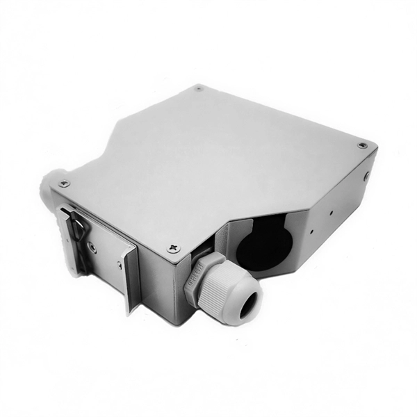
Fixing bracket on the back of the distribution box
How to install the mounting bracket? Many engineers don't know how to install this accessory. With the latest design, it can be confusing. Mounting bracket is a flexible structure, which makes it easy to adjust or replace the electrical components. All the components, wires and connections are under the protective cover due to the same height. The BBT-HF telescoping bracket, used with the BBA and BBA-4 box mounting brackets, provides an extremely flexible, fast rough-in solution. more Charlie DIYte (CharlieDIYte) tagged products below. Make sure the walls are strong enough to bear the weight of the box and electrical equipment. Ground. Electrical box screw mounts broke, can it be fixed without tearing up wall? I was unplugging an appliance in the kitchen when the whole outlet pulled out of the wall. Second photo shows my temp.
-
Spacing of the side of the distribution box
Side clearance: There should be a minimum of 30 inches of clearance from the sides of all electrical equipment, but in no case less than the width of the equipment itself. This is referred to as the side-to-side working space. In industrial power distribution systems, cable distribution boxes (also known as power distributor boxes, distribution electrical boxes, or electrical power distribution boxes) are the core hub of power transmission, branching, and protection. Its layout directly affects the efficiency of the. NEC Article 314 establishes requirements for the installation and use of electrical boxes, conduit bodies, fittings, and handhole enclosures. NEC Article 408. Boxes distribute low currents in an area equipped with 1 to 12 RJ 45 sockets. They centralise connections to ensure flexibility and that the installation is up to date.
[PDF Version]
-
Selection Guide for OSFP and QSFP Optical Modules Used in Supercomputing Centers
This article compares OSFP and QSFP-DD in terms of physical dimensions, power and thermal characteristics, and compatibility, providing practical guidance for data center and network infrastructure planning. In the rapidly evolving landscape of high-performance computing and AI infrastructure, NVIDIA optical transceivers have emerged as critical components for enabling next-generation 800G network deployments. This guide gives you the complete picture. Our study of OSFP transceiver technology will begin with basic concepts and continue until we reach advanced technical. Today's mainstream 400G optical modules use three primary form factors: QSFP-DD, OSFP, and QSFP112. This article provides a comprehensive comparison of the three. In 2025, the optical transceiver market has shifted decisively. On the path to the 400G era, different form factors act as distinct engines, delivering.
[PDF Version]