-

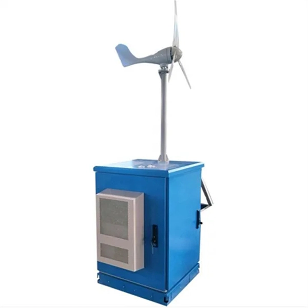
How many days does it typically take for the relay protection system of a power plant to recover
The magnetic system in induction disc overcurrent relays is designed to detect overcurrents in a power system and operate with a pre-determined time delay when certain overcurrent limits have been reached.OverviewIn, a protective relay is a device designed to trip a when a is detected. The first protective relays were electromagnetic devices, relying on coils operating on moving par. Electromechanical protective relays operate by either, or. Unlike switching type electromechanical with fixed and usually ill-defined operating voltage thresholds. Electromechanical relays can be classified into several different types as follows: "Armature"-type relays have a pivoted lever supported on a hinge or knife-edge pivot, which carries a moving contact. These relays may.
-
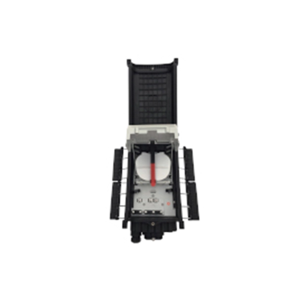
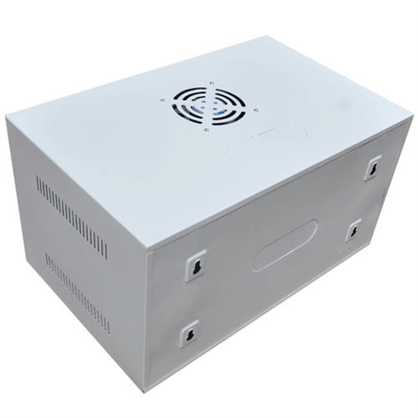
The power cable enters from the bottom of the distribution box
Cables can enter the structure from the floor (bottom entry) or from above (top entry. ) Distribution structures divide and send power to branch circuit protection devices and then to branch circuits to power downstream loads. Power. When installing a new overhead combination service for a residential service replacement we were told by the EI that we could not install our romex cables coming from under the house in a single 2" pipe approx. The scope of the article includes electrical requirements related to: Below is a complete overview. Once the box is securely in place, it's time to bring in the cables that will carry current from the main panel. Escape will cancel and close the window. Power from the utility company is typically delivered through three large conductors, which may enter the house overhead or underground. Overhead service. Fixed to a wall—This is a common approach for small electrical distribution boards. For bottom entry, the floor can incorporate a trench or false floor, which is often simpler since it provides.
[PDF Version]
-

Manufacturer of steel cable trays for nuclear power plants
Nova, a product and service brand of Curtiss-Wright Nuclear, supplies safety-related cable tray systems that are manufactured to current NEMA VE1 specifications to the nuclear industry and other power generation industries. With over 210,000 feet of straight tray and over 2 million tray fittings. MP Husky is a founding member of the USA Cable Tray Institute and the leader in US cable tray systems and cable support systems. Designed to fulfill diverse needs of industrial, commercial, and specialized sectors, these systems offer unmatched performance, safety, and durability. Twenty nine years and over 30 patents later, Snake Tray is the market leader. Our company integrates R&D, production, and sales, and has professional technical personnel and an experienced management team. Our main products include cable trays, seismic supports, C-channel steel, and.
[PDF Version]
-
Power Plant Dual Relay Protection Configuration Standards
IEEE Std 242 - 2001 IEEE Buff Book–IEEE Recommended Practice for Protection and Coordination of Industrial and Commercial Power Systems IEEE Std C37. 95-2002 (R2007)Power System Protective Relays: Principles & Practices Protective Relays - Technical Seminar Nov 2016 - Copyright: IEEE 1 Power System Protective Relays: Principles & Practices Presenter: Rasheek Rifaat, P. Eng, IEEE Life Fellow IEEE/IAS/I&CPSD Protection & Coordination WG Chair Jacobs Canada. This document supplements PJM Manual 07 which contains the minimum design standards and requirements for the protection systems associated with the bulk power facilities within PJM. This document provides recommendations, background and philosophy on relay protection that is not available in M07. Consideration is given to availability and location of breakers, current sensing devices, and disconnect switches, as well as bus-switching scenarios, and their impact on the selection and application of bus protection. Its modular design and powerful DIGSI 5 engineering tool provide tailored solutions. You will get a list of all suitable products!.
[PDF Version]
-

Four Principles of Power System Relay Protection
Differential Relay: Compares currents at two points; operates when there is a difference (used in transformers and generators). com IEEE Southern Alberta Section PES/IAS Joint Chapter Technical Seminar - November 2016 Protective Relays - Technical Seminar Nov 2016 - Copyright: IEEE 2 Abstract: Protective relays and devices. Recognized under 2(f) and 12 (B) of UGC ACT 1956 (Affiliated to JNTUH, Hyderabad, Approved by AICTE - Accredited by NBA & NAAC – 'A' Grade - ISO 9001:2015 Certified) Maisammaguda, Dhulapally (Post Via. Kompally), Secunderabad – 500100, Telangana State, India To introduce all kinds of circuit. protective system, Components of Protection System. Sequence Components and Fault Analysis: sequence impedance, fault calculations, Single line to ground fault, Line to ground fault with Zf, Faults in Power syst ional relays, Distance relays, Differential relays. Eng, IEEE Life Fellow IEEE/IAS/I&CPSD Protection & Coordination WG Chair Jacobs Canada, Calgary, AB rasheek. Sensitivity refers to the minimal changes in measured parameter that the system can react to.
[PDF Version]
-
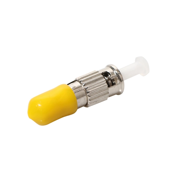
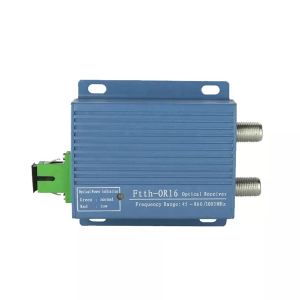
How are optical power meters classified
An optical power meter (OPM) is a device used to measure the power in an signal. The term usually refers to a device for testing average power in systems. Other general purpose light power measuring devices are usually called,, power meters (can be sensors or ), or lux meters. A typical optical power meter consists of a , measuring and display. The sens.
-
Light collection power of the second-stage beam splitter
It is currently used in modern three-CCD cameras. An optically similar system is used in reverse as a beam-combiner in three- LCD projectors, in which light from three separate monochrome LCD displays is combined into a single full-color image for projection.OverviewA beam splitter or beamsplitter is an that splits a beam of into a transmitted and a reflected beam. It is a crucial part of many optical experimental and measurement systems, such as In its most common form, a cube, a beam splitter is made from two triangular glass which are glued together at their base using polyester,, or urethane-based adhesives. (Before these synthetic,. Beam splitters are sometimes used to recombine beams of light, as in a. In this case there are two incoming beams, and potentially two outgoing beams. But the amplitudes.
-
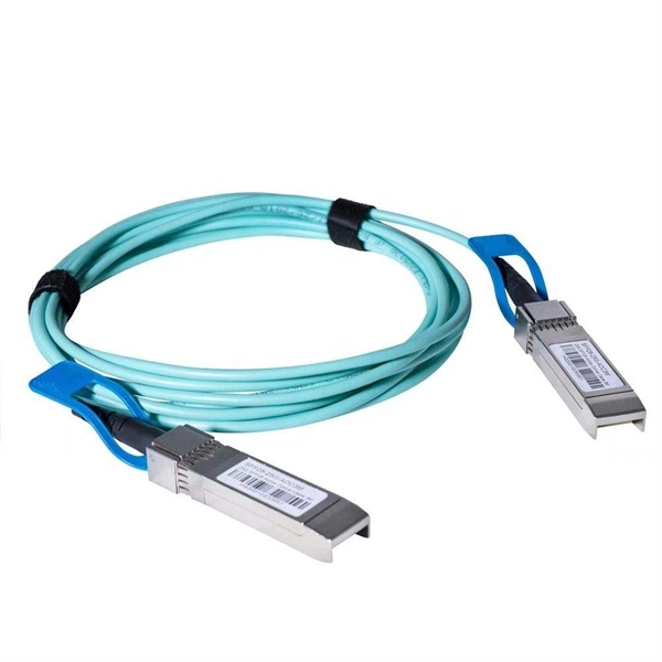
How to pull up a power fiber optic cable
Fiber optic cables should always be pulled by the strengthened yarn fibers inside the outer jacket. This article explores recommendations for pulling and installing fiber optic cable. Most fiber optic cables boast a pull strength of 100 – 200. Fiber optic cable is surprisingly strong, durable and pliable; however, several best practices should be followed to ensure a successful cable installation. Most fiber damage does not come from normal operation after the system is live. More than half of cable problems happen because of wrong pulling. In 2025, new tools like hydraulic blowers, smart monitors, and better grips help you lower risks, save money, and keep the. A duct is available from point A to point B, a pull tape is blown in, a fiber optic cable is attached to it and the cable is pulled through the duct.
-
DC busbar power failure
If the busbar protection fails to trip when an external fault occurs or if it falsely trips while in use, the power system could become unstable. A total power outage will result from this. Regular dielectric testing is crucial to verify the quality of insulation and ensure that busbars can perform reliably under both normal. Busbar insulators are the backbone of electrical systems, ensuring safe power distribution by isolating conductors and preventing faults. However, harsh operating conditions, material degradation, and improper maintenance can lead to insulator failures—jeopardizing safety and system reliability. The DC-link capacitor selection is one of the first and most important steps. Consequently, power busing design needs critical consideration in terms of performance under converter operation, asymmetric loading, short-circuits, thermal and insulation breakdown.
[PDF Version]
-
How to route large power cable trays
Learn how to install cable trays for large-scale projects with our professional, step-by-step guide covering industry standards, safety protocols, and efficient routing techniques. This guide covers the critical steps, from selecting the right electrical cable tray and performing accurate cable fill. Cable tray installation implies the construction of an electric road that will be safe. The beginning of success is to review the Bill of Quantities (BOQ) so that. Cable tray systems provide a safe, organized, and flexible method for supporting insulated conductors and cables in commercial and industrial electrical installations.