-
Should the cable management rack be installed in the front or the back
Leave space for cable management —especially in the back. Ensure front-to-back airflow by leaving gaps or using filler panels. This method helps maintain neatness and accessibility within the rack while ensuring efficient airflow and ease of maintenance. Both overhead and under floor pathways should be designed to support the weight of cables in the initial installation and it should also facilitate the addition of future cables. With proper design and structured tools, it helps organize cables, ensure stable signal transmission, simplify maintenance, and improve overall system. Here are some best practices for rack placement: Implementing hot and cold aisle containment is a fundamental strategy for improving airflow and cooling efficiency. The racks should be positioned in a way that optimizes.
-
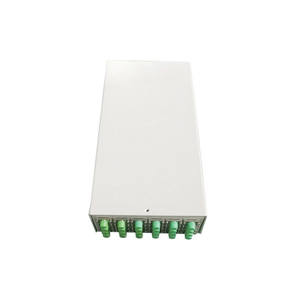
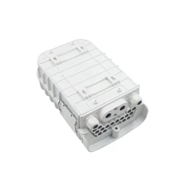
Fixing bracket on the back of the distribution box
How to install the mounting bracket? Many engineers don't know how to install this accessory. With the latest design, it can be confusing. Mounting bracket is a flexible structure, which makes it easy to adjust or replace the electrical components. All the components, wires and connections are under the protective cover due to the same height. The BBT-HF telescoping bracket, used with the BBA and BBA-4 box mounting brackets, provides an extremely flexible, fast rough-in solution. more Charlie DIYte (CharlieDIYte) tagged products below. Make sure the walls are strong enough to bear the weight of the box and electrical equipment. Ground. Electrical box screw mounts broke, can it be fixed without tearing up wall? I was unplugging an appliance in the kitchen when the whole outlet pulled out of the wall. Second photo shows my temp.
-
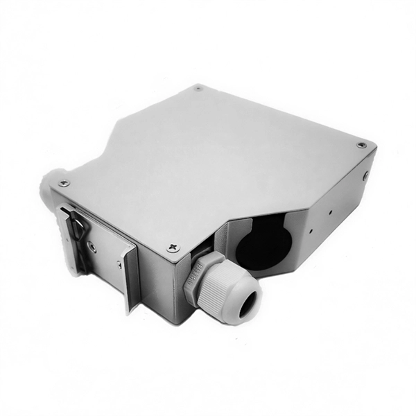
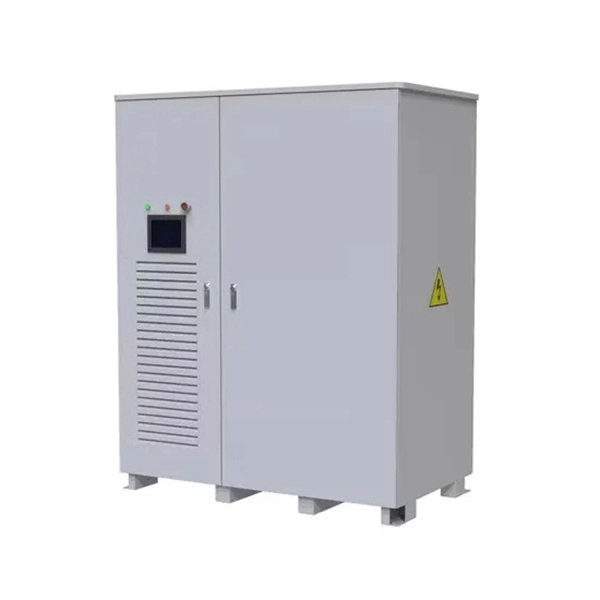
The power cable enters from the bottom of the distribution box
Cables can enter the structure from the floor (bottom entry) or from above (top entry. ) Distribution structures divide and send power to branch circuit protection devices and then to branch circuits to power downstream loads. Power. When installing a new overhead combination service for a residential service replacement we were told by the EI that we could not install our romex cables coming from under the house in a single 2" pipe approx. The scope of the article includes electrical requirements related to: Below is a complete overview. Once the box is securely in place, it's time to bring in the cables that will carry current from the main panel. Escape will cancel and close the window. Power from the utility company is typically delivered through three large conductors, which may enter the house overhead or underground. Overhead service. Fixed to a wall—This is a common approach for small electrical distribution boards. For bottom entry, the floor can incorporate a trench or false floor, which is often simpler since it provides.
[PDF Version]
-
Spacing of the side of the distribution box
Side clearance: There should be a minimum of 30 inches of clearance from the sides of all electrical equipment, but in no case less than the width of the equipment itself. This is referred to as the side-to-side working space. In industrial power distribution systems, cable distribution boxes (also known as power distributor boxes, distribution electrical boxes, or electrical power distribution boxes) are the core hub of power transmission, branching, and protection. Its layout directly affects the efficiency of the. NEC Article 314 establishes requirements for the installation and use of electrical boxes, conduit bodies, fittings, and handhole enclosures. NEC Article 408. Boxes distribute low currents in an area equipped with 1 to 12 RJ 45 sockets. They centralise connections to ensure flexibility and that the installation is up to date.
[PDF Version]
-
Color order of optical fibers and pigtails
This guide explains the latest EIA/TIA-598-D fiber color-coding standard used to identify fiber types, inner fiber sequences, and connector polish styles. With clear tables and updated details, it serves as a comprehensive reference for technicians handling modern fiber optic. Understanding fiber‑optic color codes is essential for any technician tasked with installing, maintaining, or troubleshooting modern fiber networks. In the photos above, on the left is a 1728 fiber cable with color coded buffer tubes, in the center are (from the top) singlemode zipcord cable used for patchcords with each fiber color coded, and on the right, a yellow. The color arrangement for optical fiber cables is standardized to ensure consistent identification of individual fibers during installation, splicing, and maintenance. Fiber optic cables are the arteries of modern communication—from data centers to factories, these slim strands of glass move terabits of information every second.
[PDF Version]
-
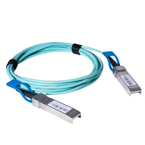
Correct wiring method for jumpers fiber optic cable
Three Polarity Connections Different polarity methods use different kinds of MPO trunk cables. However, all methods utilize duplex patch cords to form fiber optic links. The TIA standard also defines two different types of LC or SC duplex fiber optic patch cords to complete. optic cable is sensitive to excessive pulling, bending, and crushing f rces. Consult the cable specification sheet for the cable you are installing Do not bend the cable more sharply than the minimum recomme ded bend radius. Patch cords are more prone to damage than fiber optic cables, especially. Good management of fiber jumper can not only reduce the operating cost of the entire fiber optic network, make it beautiful and convenient, but also increase the reliability and flexibility of network operation and maintenance. Fiber Cabling and Management In the process of installing and arranging. The Fiber Optic Association, Inc. There are various kinds of fiber jumper cables, including single mode and. How to connect the fiber optic jumper?Optical fiber jumper is a connection line used to connect optical fiber equipment,which plays a vital role in optical fiber communication.
[PDF Version]
-

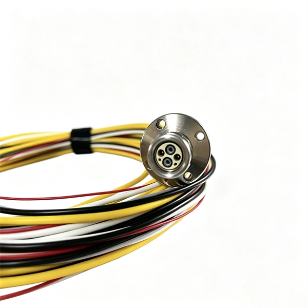
Correct Use of Pigtail Cables
Use pliers to twist wires clockwise until they form a tight spiral. This creates a solid mechanical bond. Trim any sharp edges with diagonal cutters – smooth surfaces prevent insulation damage. It ensures a secure connection by combining wires with a wire connector, like a twist-on connector or a wire nut, and then linking them to the intended terminal or fixture. This technique is often employed when three or more wires need to be joined, ensuring that the. Type W Cable: Our Type W Cable has a single conductor that's composed of thousands of strands of copper, which makes it incredibly flexible and easy to work with. Our 4/0 AWG cable, for example, has up to an impressive 2,200 strands of copper! Plus, it's wrapped in a tough Chlorinated Polyethylene. Pigtails act as bridges, allowing you to connect several wires to a single point without overloading connections. A. An electrical pigtail connector is a short length of wire — pre-terminated on one or both ends — used to extend, repair, or adapt a wiring connection. The alternative would be to attach the conductors directly to the device.
[PDF Version]
-

Correct Method for Testing Optical Power Meter Readings
Use an optical power meter for this task. You use it to measure the strength of light signals in fiber optic cables. The basic process is straightforward: turn the meter on, set it to the correct wavelength, clean your connectors, plug in, and read the. FOA "Quickstart Guides" are short, simple guides to basic fiber optic tests.