-
Austrian Fiber Optic Cable Testing Agency
As an independent testing and research institute, OFI accompanies innovation processes from the idea to market entry and beyond. We are here for you. The company ets was founded by Dipl. -Ing Franz Bauer in march 1999. 110kV as. Based on CTI test reports OVE offers various approval marks and as member of IEC and CENELEC provides access to European and international certification schemes like: The Austrian Safety Mark is a synonym for safety and quality of electrotechnical products. With professional engineering and consulting expertise, AIT is a reliable partner in the product.
-
Micro-relay protection commissioning regulations
The new protection relay functional standards are designated as the IEC 60255-1xx series. The standardisation of various test methodologies and measurement metrics promises benefits for the entire protection relay community. Relay systems protect high-voltage equipment and transmission lines to ensure safe, stable systems. Ensuring that. Abstract—Performing tests on individual relays is a common practice for relay engineers and technicians. A total of fifty international experts from seventeen national committees. Transmission and Distribution interconnections to PG&E require reliable relays to protect the electrical system for faults in the system or in the interconnected facilities as well as safeguard the service quality of other customers during abnormal operating conditions.
-

Main protective measures for optical cables
Maintain accurate as-built drawings and GPS coordinates for all buried cable routes. This prevents accidental cuts during future excavation. Cable protection extends beyond the fiber itself—connectors, splices, and enclosures must be safeguarded from environmental and mechanical. Fiber optic cables enable high-speed, long-distance data transfer, forming the backbone of modern communication. This guide covers how to. es conform to the guidelines expressed in the American National Standards Institute document (ANSI Z535) for hazard alert messages. Alerts are included in this instru d ath or serious i jury ectacles) conforming to ANSI Z87, for eye protection from accidental injury wh n ha dling chemicals, cab. Improper use of the connector end face on pigtailed fibers, e. Use of inferior quality fiber optic connectors. ESD damage is a major issue that can degrade the. It is important for fiber optic technicians to follow safety practices to avoid injuries and accidents.
[PDF Version]
-
Testing Standards for Power Fiber Optic Cable Trunk Lines
FOA procedures, such as OFSTP-7 (single-mode) and OFSTP-14 (multimode), align with TIA and IEC standards. FOA standards help you with installation, testing, and troubleshooting in real-world conditions. These parameters ensure your network meets performance and compliance requirements. You need to measure how much signal is. d suppliers of electrical construction services. Existence. ANSI/TIA‑568. 3‑E “Optical Fiber Cabling and Components Standard” was developed by the TIA TR‑42. Scope: This Standard specifies performance, transmission, and test and measurement requirements for premises optical fiber cable. A practitioner-level walkthrough of the IEC 60794 framework: standard structure, mechanical and environmental test methods, type vs routine testing, common failure modes, and procurement specification guidance. Fiber optic testing of a newly installed system not only verifies that the system meets its design requirements, but also creates a performance baseline for all future testing and troubleshooting of t at system. The Contractor must utilize the correct equipment and testing techniques to gain acceptance, or the work cannot be approved.
[PDF Version]
-

Aluminum Spectrometer External Testing
Spectrometers for Aluminium Testing, particularly Optical Emission Spectrometers (OES), are invaluable in achieving this. It ensures that each batch meets required specifications without compromising material integrity. The instrument takes advantage of modern CCD technology combined with the lates generation of readout electronics. The innovative optical system covers the entire usable wavelength range to enable selection of the best analytical wavelengths paired r numerous. Standard Test Method for Analysis of Aluminum and Aluminum Alloys by Inductively Coupled Plasma Atomic Emission Spectrometry (Performance Based Method) 5. Continuing this long tradition of excellence, the Thermo ScientificTM ARL iSparkTM 8860 Metal Analyzer is the trusted standard, which also integrates the latest innovatio cover your current and future needs in the. The energy dispersive X-ray fluorescence spectrometer (EDXRF) is widely used for quality control of aluminum alloys and acceptance inspections of recycled materials. However, analysis of light elements (particularly Mg) had been difficult until now due to the inadequate sensitivity and resolution.
[PDF Version]
-
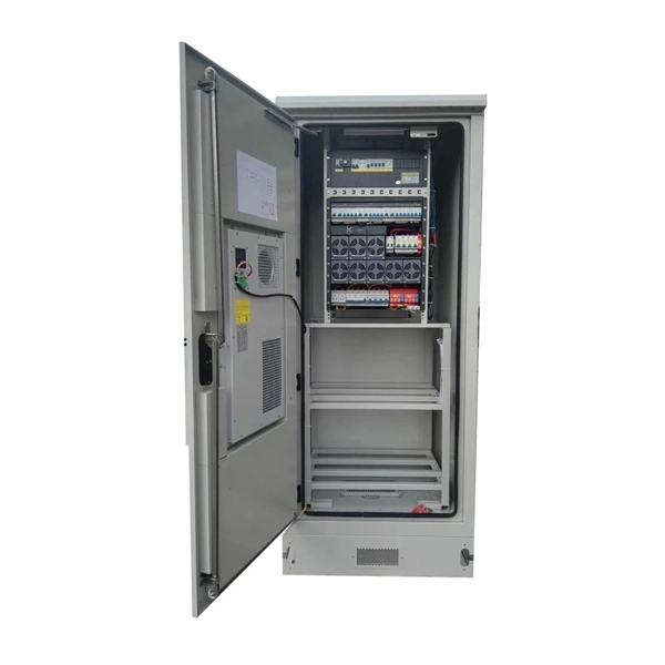
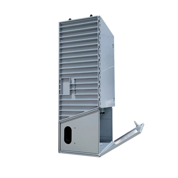
10kV Busbar Voltage Testing Standard
IEC 61439 is a standard developed by the International Electrotechnical Commission (IEC) that covers design verification for low-voltage electrical products and assemblies. The IEC 61439. 7 cycles of 24 h each to salt mist test according to IEC 60068-2-11; (Test Ka: Salt mist), at a temperature of (35 ± 2) °C. The test shall be carried out according to IEC 60068-2-2 Test Bb, at a temperature of 70 °C, with natural air circulation, for a duration of 168 h (7 days) and with a recovery. ULTRUS™ helps companies work smarter and win more with powerful software to manage regulatory, supply chain and sustainability challenges. Consistent performance benchmarking testing capabilities for professional PC users. Award-winning software and advisory services for ESG management and. The purpose of this method is to verify the functionalities of a Metal Enclosed Busb ar. How do you check and maintain busbars? What are the faults of busbar? What is bus bar in DB? For complete safety instructions and precautions, always refer to the test equipment instruction manual.
[PDF Version]
-
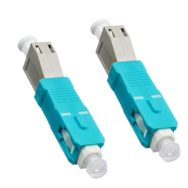
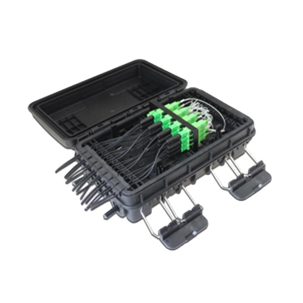
What are the testing methods for pigtail splicing
To test fibre splicer quality, begin by inspecting cleave angles and fibre cleanliness. Next, confirm arc calibration and alignment using the splicer's splice loss estimation. Follow up with OTDR or ILM testing to validate results. This guide covers everything: what fiber optic pigtails are, how they differ from patch cords, which connector and polish type to specify, how to choose between mechanical and fusion splicing, and the real-world applications where pigtails are the right call. The Contractor must utilize the correct equipment and testing techniques to gain acceptance, or the work cannot be approved. Either joining method must have three primary characteristics. The most efficient way to terminate a fiber run is by using a pigtail.
-
Internal relays of relay protection devices
The fault can be located upstream or downstream of the relay's location, allowing appropriate protective devices to be operated inside or outside of the zone of protection.OverviewIn, a protective relay is a device designed to trip a when a is detected. The first protective relays were electromagnetic devices, relying on coils operating on moving par. Electromechanical protective relays operate by either, or. Unlike switching type electromechanical with fixed and usually ill-defined operating voltage thresholds. Electromechanical relays can be classified into several different types as follows: "Armature"-type relays have a pivoted lever supported on a hinge or knife-edge pivot, which carries a moving contact. These relays may.