-
Fireproof cable trays need to be re-inspected
The inspection phase ensures the trays meet quality and safety requirements. It involves several key steps: Coating Quality: Check for cracks, peeling, or bubbles. This comprehensive checklist helps facility managers and maintenance personnel identify potential issues with fire-rated cable tray covers before they lead to. This guide explains the critical steps in fireproof cable trays acceptance, covering coating processes, inspection standards, and more. Fireproof cable trays are specialized structures designed to. The Occupational Safety and Health Act requires employers to comply with safety and health standards promulgated by OSHA or by a state with an OSHA-approved state plan.
-
German Fireproof Galvanized Cable Tray Specifications
The DIN Standard 4102 part 12 defines the requirements and testing method for fire resistance of electric cable support sys-tems required to maintain its integrity. The standard, limited to 1KV, specifies 3 categories of functional maintenance as fol-lows: E30, E60 and E90. us-trations without notice. The mechanical and electrical characteristics, tests, certifications, overall quality management, recommendations mentioned. Until the European standard is published, VERGOKAN uses, the DIN 4102-12 Standard to test and certify the preservation of functionality of its installations. Sizes and designs can be customized and special dimensions are. Cablofil cable tray is the preferred choice for the cable containment of low and high voltage electric cables where fire resistance is crucial - this includes cable basket tray systems for Prysmian FP (FP400 and FP600) and Draka Firetuf type cables. Cablofil fire resistant and fire proof cable. inc coating by means of a continuous ipping process. This zinc coating is easily deformed. A cathodic action occurs on cut s leaned and roughened in order to achieve a good bond.
[PDF Version]
-
What type of cable tray is fireproof
Fire resistant cable trays are cable trays with fire-resistant boards as the core protective layer. Data centers house sensitive equipment such as servers, switches, and storage devices, all of which require a constant and reliable power. NewReach has created a fire-rated cable tray designed to maintain its structure during a fire. This tray effectively prevents the spread of flames for a specified duration. Core Fire-Resistant Layer: The inner layer is wrapped with. Cablofil cable tray is the preferred choice for the cable containment of low and high voltage electric cables where fire resistance is crucial - this includes cable basket tray systems for Prysmian FP (FP400 and FP600) and Draka Firetuf type cables.
-
Fireproof cable tray fire resistance duration
20 min that does not exceed 150 m2, and a peak smoke release rate that does not exceed 0. 3 ft2/sec) when tested using the FT4/IEEE 1202 flame test in either UL 1685 or UL 2556. Focuses on fire resistance, including burn duration and flame spread. Measures smoke, acid gas, and toxic gas emissions. International standard defining general fire performance requirements for cable trays. If your cable trays don't meet these standards, they could fail when exposed to fire. Must be listed as having adequate fire resistance and low-smoke producing characteristics by exhibiting a. The UL 1257 testing standard evaluates the performance of cable tray and conduit assemblies in a fire environment by subjecting them to various temperature conditions. Core Fire-Resistant Layer: The inner layer is wrapped with. Where cables pass through shafts, walls, slabs, or enter electrical panels or cabinets, openings shall be tightly sealed with firestopping materials in accordance with design requirements.
[PDF Version]
-

Near the fireproof bridge in Ukraine
On 12 August, the bridge was the target of a missile attack. The bridge was fully reopened on 14 October. Another explosion occurred on 3 June 2025 near the support pillars, but by evening traffic returned to normal. Ukraine claimed responsibility for all three explosions.OverviewThe Crimean Bridge, also called Kerch Strait Bridge or Kerch Bridge, is a pair of parallel bridges, one for a four-lane road and one for a double-track railway, spanning the between the had been considered since the early 20th century. During World War II the German built a over the strait. Finis. After the annexation, Russian officials looked at various options for connecting Crimea to the Russian mainland, including a tunnel, but eventually settled on a bridge. The bridge spans the between the.
-
Fireproof Sealing Procedures for Cable Trays
Cable trays and busways at floor level or at slab penetrations shall have a waterstop no less than 50 mm in height. At slab penetrations, provide 20–30 mm of firestopping and install a fire-support plate at the top. Sealing shall be tight and reliable, without visible. Scope: Firestopping for busway, cable trays, cables, and trunking passing through walls in enclosed electrical installations. These systems prevent fire and smoke from spreading through open cable pathways, maintaining circuit integrity and code. Fireproof cable trays play a crucial role in modern electrical systems. * Two (2) sticks of moldable putty (part number FSP-MPS) are also needed for each opening. Route Planning and Layout Principles Coordinate with Building Structure: Cable tray routing should align with architectural design, avoiding unnecessary. SLIPSIL Sealing Plugs are an ideal solution for the fire-safe, gas and / or watertight sealing of penetrations carrying single or multiple pipes. A better alternative to link-type seals, the SLIPSIL Plugs utilize a proprietary self-compression design, and have no bolts, nuts or metallic parts that.
[PDF Version]
-

Rwandan Fireproof Cable Tray Specifications
It is the cable tray with the highest number of certifications and specifications in the world: RETIE, UL, ANCE, ETL, NEMA, ROHS. Fire resistance: Cablofil is certified E30 - E90, through temperature rise tests up to 1000°C for 90 minutes. us-trations without notice. All illustrations, descriptions and technical information included in this document are provided as indications and can cable trays are equivalent. The mechanical and electrical characteristics, tests, certifications, overall quality management, recommendations mentioned. The Cablofil Cable Tray System is constructed with high quality steel and precision engineering. The prefabricated design consists of modules joined together with eccentric locks or tightening bands. We have a highly experienced team, well-loaded manufacturing unit and a lot more to match up the ever-evolving needs of our customers. Moreover, our focus on maintaining high quality and.
[PDF Version]
-
Fireproof cable tray production qualification
This guide explains the critical steps in fireproof cable trays acceptance, covering coating processes, inspection standards, and more. By following these steps, you can enhance durability and comply with national safety requirements. us-trations without notice. All illustrations, descriptions and technical information included in this document are provided as indications and can cable trays are equivalent. Fireproof cable trays are specialized structures designed to. The following charts give the number of 3M pillows needed to completely firestop an opening that cable tray passes through. UL Listed Systems Concrete Wall - C-AJ-4056 3 HR F-Rating, 3/4 HR T-Rating Gypsum. Cable tray installation must comply with specific technical standards to ensure electrical safety, system reliability, and long-term maintainability. 305(a)(3), or comparable standards promulgated by States operating OSHA-approved State plans.
[PDF Version]
-
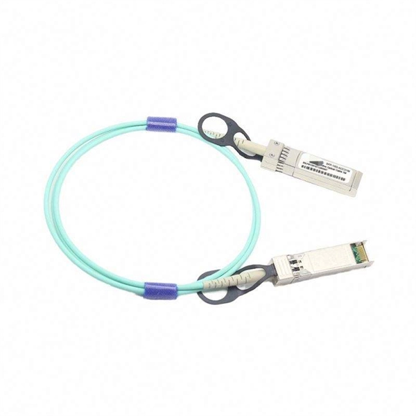
How to test a properly spliced optical cable
The most common methods for testing fiber optic splices are optical time-domain reflectometry (OTDR) and optical loss test set (OLTS). For every fiber optic cable plant, you will need to test for continuity, end-to-end loss and then troubleshoot the problems. If it's a long outside plant cable with intermediate splices, you will probably want to verify the individual splices with an OTDR also, since that's the only way to make. That's where splicing comes in—and knowing how to properly splice a fiber optic cable is a critical skill for any technician. Splicing allows you to restore or expand fiber networks while maintaining signal integrity. Fiber optic testing of a newly installed system not only verifies that the system meets its design requirements, but also creates a performance baseline for all future testing and troubleshooting of t at system.
[PDF Version]
-
Fiber optic cable test chart to check for broken ends
Use a Fiber Inspection Microscope – 200–400× magnification reveals scratches or pits on ferrule end-face. Visual Fault Locator (VFL) – Injects a red laser (650 nm); light leakage indicates bend, crack, or break. The process of testing any fiber optic cable plant during and after installation includes all the procedures covered so far. As network speeds and bandwidth demands increase, fiber performance requirements have become more stringent. Corning recommends that all fiber optic systems be tested to a minimum set. Here are the most common fiber optic testing methods used by network professionals: Conducting a visual inspection test involves using a fiber scope or microscope to examine the endfaces of connectors for dirt, scratches, or cracks. Cable contamination can also.
-
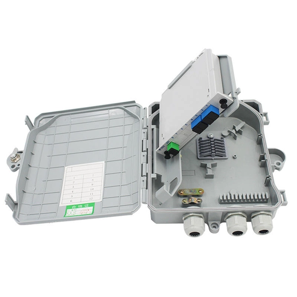
Distribution Box Ground Resistance Test
The selective testing method uses one clamp and two stakes. It allows you to measure the ground resistance at specific parts of an installation, isolating the system to check or reference what's in place. Th.
-
Latest Standards for Relay Protection Withstand Voltage Test
IEC 60255-5 is the standard that defines insulation coordination for these devices — the test voltages, impulse withstand levels, and minimum insulation resistance values that every protection relay must meet. This article breaks down the standard's requirements with the specific clause numbers and. Abstract: Design tests for relays and relay systems that relate to the immunity of this equipment to radiated electromagnetic interference from transceivers are specified in this standard. Two types of tests are specified: the oscillatory (SWC) and. IEEE Standard for Relays, Relay Systems, and Control Devices used for Protection and Control of Electric Power Apparatus--Surge Withstand Capability (SWC) and Electrical Fast Transient (EFT) Requirements and Tests Abstract: Design tests for relays, relay systems, and control devices used for.
[PDF Version]