-
Grounding rectification measures for distribution boxes
First, we review and compare medium-voltage distribution-system grounding methods. Whether you're a seasoned pro or just starting out, this comprehensive guide will give you practical insights into proper grounding techniques, with a special focus on how selecting quality materials from a reliable building material supplier impacts your entire system's safety and longevity. Power from factory ground must be installed by a qualified electrician. We then analyze the behavior of ungrounded systems under ground fault. Ground rods are the most common grounding electrode found on distribution circuits. This chapter describes general grounding installation requirements for. An equipment grounding conductor passing through the box without a splice is not required to be joined inside the box to others that are spliced in the box.
-

How long should the grounding of the secondary distribution box be
The most common components of a GES are ground rods, which must be at least 8 feet in length and driven fully into the earth. If a single ground rod does not achieve a resistance to earth of 25 ohms or less, a second rod must be installed, separated from the first by a. A sub panel is a secondary distribution point that receives power from the main service panel, allowing for the extension of electrical service to a remote area of a building or a separate structure like a garage or shed. All grounding and bonding work must comply with NEC Article 250. Image used courtesy of Pixabay What Are Ground and Grounding? The. We earth ground systems to the earth to reduce overvoltage (from lightning induced energy and other events) on the conductors and electrical components (such as transformer and motor windings) of the installation. Grounding metal parts helps drain off static electricity charges before flashover. Learn the proper electrical grounding terminologies. Two levels of secondary voltage output define which.
[PDF Version]
-

Requirements for proper grounding of distribution boxes
26 mm 2 (10 AWG) ground wire must be used, and in all other markets a 6 mm 2 must be used. On the US market, a 5. If you're working with electrical systems, you know that grounding isn't just some bureaucratic requirement—it's literally the difference between a safe, functional system and a potential disaster. Today, we're diving deep into the world of distribution box grounding, breaking down the standards. Power from factory ground must be installed by a qualified electrician. This paper is intended to give an overview of the vari-ous relationships. Updated to current 2017 NEC, and included design manual requirement to include equipment grounding conductors in all feeder and branch circuits operating under 600 volts, and other editorial and typographic revisions.
-

Grounding Standards for Distribution Box Installation
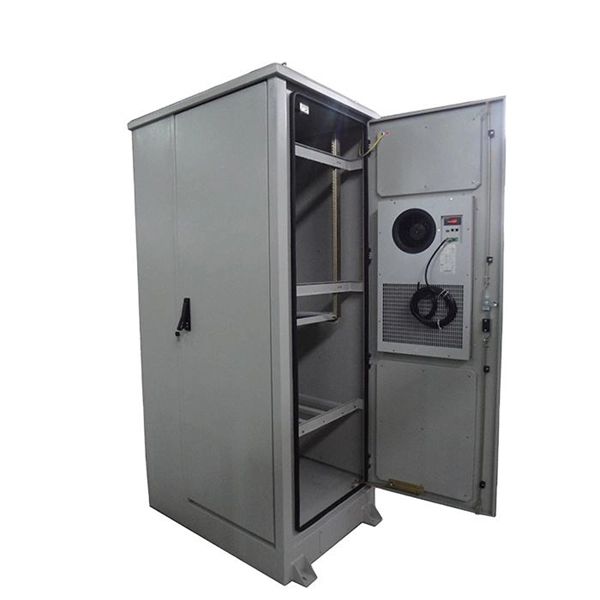
53 rules the installation of two or more grounding electrodes described in Section 250. This section also adds requirements, conditions, and restrictions to such installations. Whether you're a seasoned pro or just starting out, this comprehensive guide will give you practical insights into proper grounding techniques, with a special focus on how selecting quality materials from a reliable building material supplier impacts your entire system's safety and longevity. Each DISTRIBUTION BOX and controller must be grounded. 26 mm 2 (10 AWG) ground wire must be used, and in all other markets a 6 mm 2 must be used. Grounding of the units: Attach a ground wire from one of. To catch up on Lorenzo Mari's series on National Electrical Code 2023 Basics: Grounding and Bonding, follow these links: Section 250. This. Standards are for reference only. It takes the incoming power and safely distributes it to different circuits throughout your building.
[PDF Version]
-
Wiring the grounding plate of the distribution box
Attach a ground wire from one of the threaded studs (A) at the bottom of the housing, to the mounting plate (B). The ground resistance between all system parts. Power from factory ground must be installed by a qualified electrician. Each DISTRIBUTION BOX and controller must be grounded. 26 mm 2 (10 AWG) ground wire must be used, and in all other markets a 6 mm 2 must be used. This position is the connection point of the grounding wire in the. How to make proper & safe electrical ground wiring connections in the box: This article describes options for connecting a metal electrical box to the grounding conductor & connecting the grounding conductor to a fixture such as a ceiling light or ceiling fan. This device safely takes power from a single source, such as a generator or temporary utility service, and divides it into. Welcome to our channel! In this video, we'll walk you through the process of wiring a home distribution box with a detailed connection diagram.
[PDF Version]
-
Wiring Techniques for Three-Level Distribution Boxes on Construction Sites
Check for proper IP/NEMA ratings and material quality. Ensure safe placement: install in dry, accessible areas with good ventilation and at appropriate height (typically ~1. Practice good wiring: secure grounding, neat cable management, proper insulation, and correct wire gauge. Learn how to wire a distribution box step by step! This video shows real on-site footage of electrical installation, demonstrating safe and standardized wiring methods used by professionals. The standard. Wiring methods. The provisions of this paragraph do not apply to conductors which form an integral part of equipment such as motors, controllers, motor control centers and like equipment. Metal raceways, cable armor, and. Wire color: The neutral wire is blue, and the color of the phase wire (A phase is yellow, B phase is green, and C phase is red) should meet the standard. However, exposure to weather, frequent relocation, rough use and other condi-tions not normally encountered with conventional wiring systems necessitate special consideration not require in other applications or in completed structures.
[PDF Version]
-
Equipotential bonding of distribution box
Equipotential bonding cables are required between two control cabinets with a minimum conductor cross-section of 16 mm². This protects people from electric shock and protects equipment or systems. Equipotential bonding (EPB) is a set of electric connections intended to achieve equipotentiality between conductive parts [Source: IEC 60050-195-2021]. The British Standard BS 7671 defines the term “equipotential bonding” as follows: Equipotential bonding is an electrical connection maintaining. “In each installation main protective bonding conductors complying with Chapter 54 shall connect to the main earthing terminal extraneous-conductive-parts including the following: (i) Water installation pipes (ii) Gas installation pipes (iii) Other installation pipework and ducting (iv) Central. Equipotential bonding is the foundation of a reliable lightning protection and surge mitigation strategy. 2020 Differences in potential between separated plant components can lead to high equalizing currents over the.
[PDF Version]
-
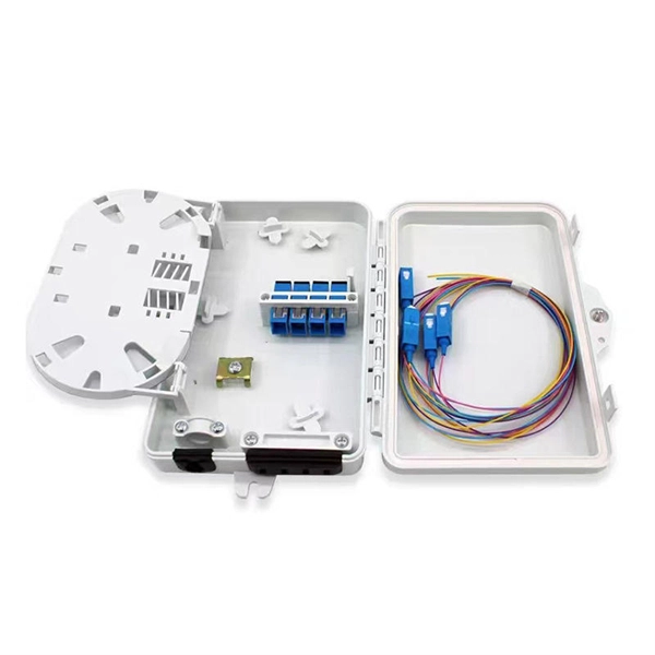
8-core optical cable splicing techniques
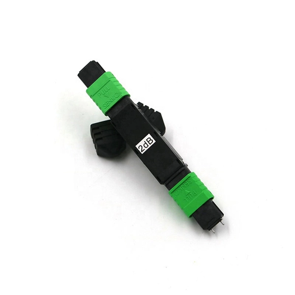
In this guide, we'll walk you through the entire process of preparing fiber optic cable for splicing and termination to fiber connectors. We'll explore the necessary tools, safety precautions, and step-by-step procedures for cable connectors, mechanical and fusion splicing methods. What is Fiber Optic Splicing and Why is it Needed? – #1. For network managers and technicians, a poor splice can lead to significant signal degradation, network downtime, and costly troubleshooting. 1dB for fusion) and degrade over time in outdoor environments. A professional splice kit includes: Every splice starts with proper preparation: clean the work area, protect against wind, and. Fiber optic splicing is the process of joining two fiber optic cables together so that light signals can pass with minimal loss or reflection. Splicing is typically required during cable installation, maintenance, or network expansion.
[PDF Version]
-

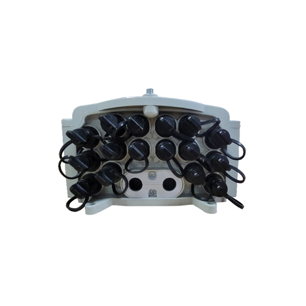
Lightning protection and grounding of mobile optical distribution boxes
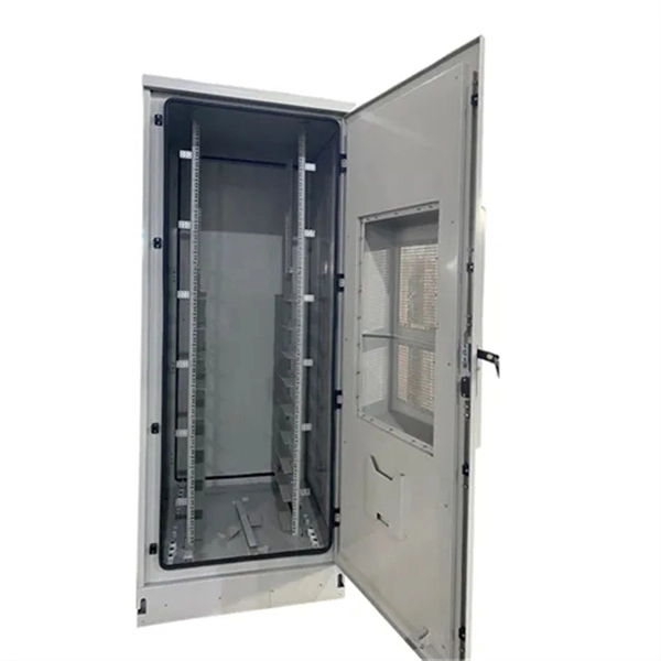
This Recommendation provides guidance on protecting indoor distribution systems for mobile communication in large-scale buildings from lightning and safety risks. It emphasizes compliance with standards like IEC 62305-3, IEC 62305-4, IEC 60364 series, and ITU-T K. 21 for effective. We make safe, reliable and high-quality solutions for every spec and project. Lightning protection needs vary according to each specific facility. It is located at an elevation such that a line passing through the static wire and the outermost conductor below it is at a 30° aximum angle with a vertical line. ERICO® has complete telecommunications applications solutions to help protect the facility against electrical noise, lightning induced surges and transients caused by. Ground rods are the most common grounding electrode found on distribution circuits.
[PDF Version]
-
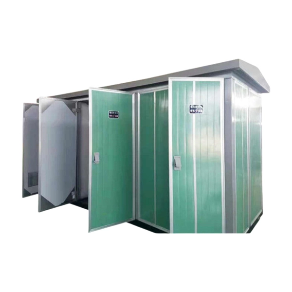
Reasons for switchgear busbar grounding
The ground bus inside metal-enclosed switchgear serves as more than a passive conductor. It determines whether personnel survive ground faults, whether protection relays operate correctly during switching transients, and whether equipment passes type testing. Grounding is one of the most crucial safety measures in electrical installations, and the bus bar. I know when you have a utilization voltage service transformer, you bond the neutral and ground buses at the service entrance equipment and from that point you are running 3P, 4W, plus an equipment ground through the whole system. The question I have is with primary switchgear used to distribute. This blog explains the difference between grounding in switchgear systems and earthing in switchgear system design, why they matter, and how they ensure reliable and safe power distribution. The neutral wire (white) and the equipment grounding conductor (EGC, bare or green) often terminate on bus bars that look. Abstract: System grounding considerations affect many aspects of an electrical system. Neutral and ground should only be connected together at one point in the electrical.
[PDF Version]
-
Which is better for grounding wire in fiber optic cables
OHGW is designed primarily to provide a grounded conductor while incorporating fiber optics for communication purposes. Dielectric means it has non-conducting properties of a non-metallic, insulating material that resists the passage of electric current. Armored fiber-optic cable bonding and grounding are simple phases in the installation process but are sometimes misunderstood or omitted. [. ] One of our readers asked us this question. "What needs to be grounded in a fiber optic network?" The standard answer of "everything" seemed illogical and was. Choosing the right Optical Ground Wire (OPGW) cable involves several considerations that cater to your specific needs and application environment. These cables include metallic components that can carry electrical currents, presenting potential hazards such as electrical shock or fire. Interlocking armor is an aluminum armor that is helically wrapped around the cable and found in indoor and indoor/outdoor cables. It offers ruggedness and superior crush resistance.
[PDF Version]
-

Standard for Grounding Resistance of Directly Buried Optical Cables
101 describes characteristics, construction and test methods of optical fibre cables for buried application. Note that Recommendation ITU-T L. This Applications Engineering Note (AE Note) discusses conventional bonding and grounding practices for conductive fiber optic cable and hardware installations within the scope of the National Electrical Code (NEC). First, in order to demonstrate sufficient performance of an. Section 250. (FOA) was founded in 1995 to help develop the workforce to build the fiber optic networks to support a rapid expansion in communications and the Internet. Keywords:acceptance testing, cable, cable installation, cable selection, communication cable, electrical. study of this important article.