-

Analysis of the causes of signal attenuation in optical splitters
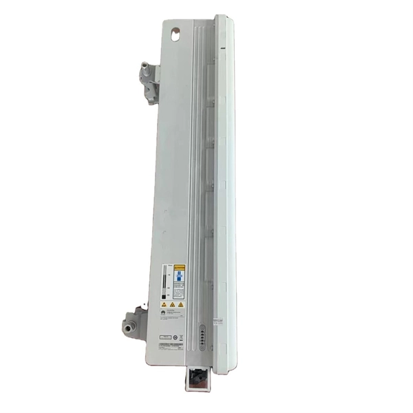
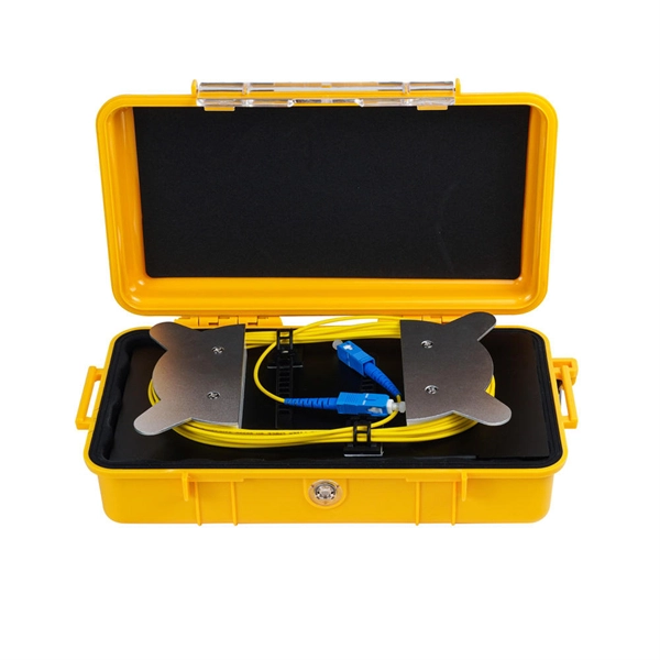
In the context of beam splitters, attenuation can occur due to several factors, including absorption, reflection, and scattering. Understanding how beam splitters affect signal attenuation and polarization is essential for optimizing systems in telecommunications, imaging, and laser applications. In the. Fiber optic splitters distribute optical power from one input fiber to multiple output fibers through either fused biconical taper (FBT) coupling or planar lightwave circuit (PLC) waveguide structures. Their performance depends on optical symmetry, waveguide integrity, and mechanical stability of. · Signal Attenuation: The loss of signal strength as it travels through the fiber can lead to poor quality communication. By careful processing, couplers that were bidirectional were made. So a 2:2 coupler would take the signal from one fiber on one side and split it between the two fibers on the.
[PDF Version]
-
Analysis of Optical Module Sensitivity Issues
This guide provides a comprehensive overview of sensitivity analysis in optical design. It involves analyzing how the performance of an optical system varies in response to changes in its design parameters. For example, SONET specifies that the BER must be 10 -10 or better. By understanding the measurement standards, influencing factors, and application. It is often useful to analyze your tolerances in detail so that you can best understand where and why sensitivities exist in your optical system. In OpticStudio's tolerance analysis, you may save the tolerance results for each Monte Carlo file, or you may save each tolerance in the sensitivity.
-
Analysis of the Four Characteristics of Relay Protection
The article first analyzes the role, composition, requirements of relay protection, and then analyzes the fault analysis of power system protection and treatment measures; the final analyzes the question of the relay protection substation operation. (1) Selectivity: refers to that when the Electrical fault occurs, the relay protection device acts and only removes the fault element. Minimize the scope of power outages as much as possible to continue the operation of non faulty parts of the system. Divide into main protection and backup. To provide effective and reliable protection to the power system, a protective relay must have the following essential functional characteristics: Selective, Fast, Stable, Reliability, Sensitivity, Simple Construction and Installation Mechanism, and Cost-effective. These are some essentially. Protective Relays - Technical Seminar Nov 2016 - Copyright: IEEE 2 Abstract: Protective relays and devices have been developed over 100 years ago to provide “lastline”of defense for the electrical systems. Therefore, the whole system has gone down, even though many circuit breakers have remained closed.
[PDF Version]
-
Analysis of Reasons for Poor Fiber Optic Cable Connections
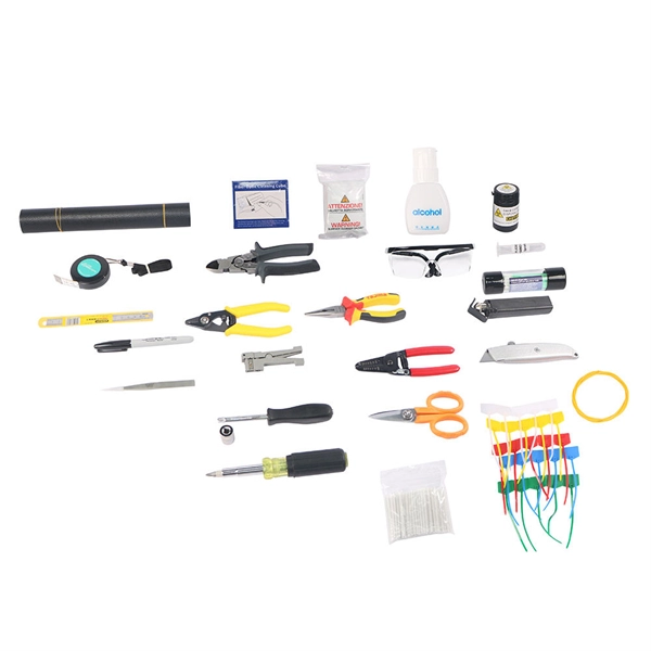
Despite their robustness, fiber networks can fail due to: Physical Damage : Cuts, bends, or contamination in fiber cables or connectors. Hardware Failures : Faulty transceivers, switches, or routers. Good troubleshooting is a sequence, not a scattershot of tests. Start with the simplest, fastest checks (visual inspection, cleaning, cable routing) and only move to instrumentation (power meter, VFL, OTDR) when those steps don't clear the fault. This saves time and prevents needless part swaps. Or it could be caused by the quality of the connector itself, such as poor end-face geometry that doesn't pass the. Fiber optic networks are known for high-speed data transmission and reliability, but they're not immune to failures. Knowing how to recognize and diagnose these problems quickly ensures. Fiber optic troubleshooting is the systematic process of identifying, diagnosing, and resolving problems within fiber optic communication networks.
[PDF Version]
-
Calculation of Angle Iron for Cable Trays
Enter the applied point load or uniform load. Choose whether to include self weight. Press calculate and review stress, deflection, and capacity. Calculate horizontal, vertical, or compound cable tray offsets based on bend angle, offset distance, and available installation space. Measure this distance along the straight tray. Hubbell Take Off Support provides the contractor, engineer, end user a completed BOM, including all related products, counts, symbol legends and information required to price a project. Don't spend the many hours required to do counts and create BOMs for projects, rely on Hubbell's take off. Cable tray (or cable ladder) systems are a popular alternative to electrical conduit systems, as they have an outstanding record for dependable service, design flexibility and cost savings in commercial and industrial applications. A properly designed and installed cable tray system will provide. Stop Costly Cable Tray Installation Errors Now: Avoiding Mistakes in Instrumentation Cable Tray Installation: A Guide for EPC Projects Cable tray sizing in real EPC projects is not limited to simple area calculation.
[PDF Version]
-
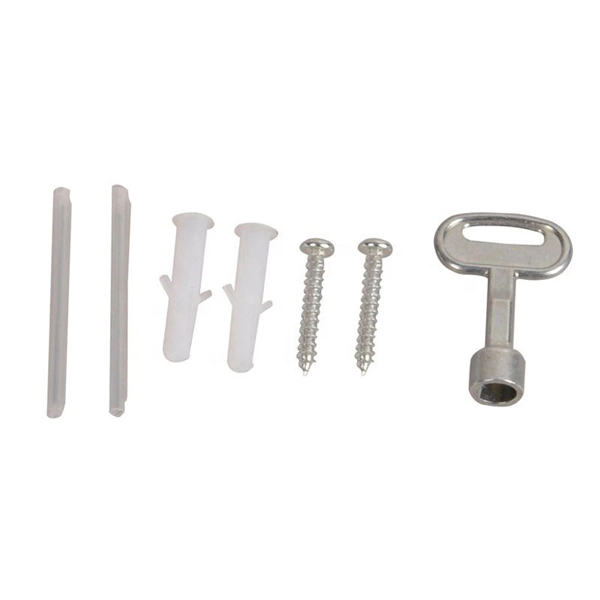
Wiring method for flat iron distribution box
Take the appropriate rating of MCB and RCCB as per your load requirements. Connect the phase and neutral wires from the input power supply to the input of the Main MCB. Connect the output of the Main MCB to the input of the. Learn how to wire a distribution box step by step! This video shows real on-site footage of electrical installation, demonstrating safe and standardized wiring methods used by professionals. Distribution Box Installation: Put the distribution box on the. Material preparation: Prepare the required circuit breakers, wires, wiring ties and other materials, and ensure that they meet the design drawings and installation requirements. Straight lengths are shipped without exterior crating.