-

Composition of butterfly-shaped drop fiber optic cable
FTTH Butterfly Optic Cables, also known as flat drop fiber cables, feature a compact flat profile with optical fibers placed at the center and reinforced by parallel strength members on both sides. Then, the cable is completed with LSZH sheath. Also, customers can specify your required connectors. Environmental Performance. Abalone Tech's 1/2/4F Self-supporting Butterfly Drop Cable is designed for aerial and duct installations in FTTH (Fiber-to-the-Home) and telecom networks. 5 kg/km Optical Performance: Insertion loss <0.
-
Maximum length of optical cable between the two stations
Fiber optic cable can be run anywhere from 300 meters up to 80 kilometers (roughly 50 miles) depending on the cable type, transceiver used, and network standard. Fiber optic cable transmission distance is determined by two primary physical factors that affect signal quality as light travels through the fiber medium. For most enterprise or data center applications using multimode fiber, the practical limit sits between 300 m and 550 m. Single-mode. Maximum length: 90 meters. Patch Cords: The short, flexible cables connecting devices to outlets (e., from a laptop to a wall port). Many factors decide the fiber cable distance, but the key factors include the below six aspects. Attenuation is the weakening of light as it comes in from the transmitting end of the fiber and out of the transmitting end. For instance, signals at 1550 nm.
[PDF Version]
-
Span cable tray load-bearing dimensions
This step‑by‑step approach helps you determine width, depth, support spacing, and allowable load with confidence. Plan 20–30% spare capacity for growth. Remember separation rules for EMI. Ladder cable tray is available in widths of 6, 9, 12, 18, 24, 30, 36, 42 and 48 inches with rung spacings of 6, 9, 12 or 18 inches. Specifiers should be aware that some cable tray. Hubbell's NEXTFRAME® Ladder Tray is the effective and widely used cable runway that supports and delivers bundles of cable between cabinets, racks, and closets, along walls, and suspended from ceilings. The Ladder Tray features light, rugged, tubular steel construction. 2 m long span tray are now also available. Is the perpendicular distance measured from inside of side member (rail) web to opposite side member web. Standard widths are 150 mm. us-trations without notice. All illustrations, descriptions and technical information included in this document are provided as indications and can cable trays are equivalent. The mechanical and electrical characteristics, tests, certifications, overall quality management, recommendations mentioned. MA VE-1.
[PDF Version]
-
Maximum number of optical fiber cores in an optical cable
Multi-core fiber optic cables can contain 3 to 12 cores within a single cable. This significantly increases the data transmission rate, making them ideal for modern, high-demand applications. Multi-core fiber optic cables can serve multiple channels simultaneously to optimize. The number of optical cores in an optical fiber is the total number of equipment interfaces multiplied by 2, plus 10% to 20% of the spare quantity, and if the communication mode of the equipment has serial communication and equipment multiplexing, you can reduce the number of cores. Understanding Fiber Cores: Core: The central glass fiber that transmits light signals. Single-mode: A. The total number of cores for a 1pc fiber patch cable is calculated as the number of branches multiplied by the number of cores per branch (if there are no branches, the number of branches = 1). The following ZR Cable introduces some methods to determine the number of fiber cores.
[PDF Version]
-

Unpacking of Drop Cable
A drop cable is the final segment of the telecommunications network that physically connects a service provider's infrastructure to a customer's property. This cable runs from a point on the utility network (such as a pole, pedestal, or vault) directly to the side of a home or. A drop cable, commonly referred to as a cable drop, is a critical component in network connectivity, typically used to connect a computer's Network Interface Card (NIC) to a wall plate. WARNING: Unrestrained cable ends may cause injury to your eyes or body and can damage the cable fitting, or fibers if suddenly released from a coil. A cable drop, also known as a last-mile cable, connects the main distribution network to individual end-users, bridging the gap. Recognizing that no two networks are alike, Clearfield has developed the industry's widest choice of drop cable solutions – speeding deployments and providing the flexibility of configuration that best suits your network environment, network design and drop cable needs.
[PDF Version]
-
Maximum allowable voltage drop value of 10kV busbar
The formula used is IMAX = (I * 100) / (100 + VD), where I is the busbar current rating and VD is the allowable voltage drop. Typical values for LV installations are given below in Figure G27. 1) These voltage-drop limits refer to normal. Instant voltage drop limits calculator: NEC and IEC compliant, auto-applies 3%/5% rules for lighting, feeders. Enter nominal voltage and optional measured drop; get pass/fail, max allowable volts, length helper instantly. Design by percent limits: compute max length, minimum size or actual drop. Voltage drop is the reduction in voltage along a bus bar due to its resistance. This standard defines the design verification, test requirements, and thermal performance of the assemblies.
-
Cable tray and hanger span refers to
The number (such as 8, 12, or 20) indicates the span or the distance between the metal hangers that contain the tray in feet. Hubbell's NEXTFRAME® Ladder Tray is the effective and widely used cable runway that supports and delivers bundles of cable between cabinets, racks, and closets, along walls, and suspended from ceilings. The Ladder Tray features light, rugged, tubular steel construction. The three main types of cable tray are: Perforated Cable Trays. What is a Cable Tray System? As per the National. association representing the major electrical equipment manufac-turers in the U. The most significant section of NEMA VE 1 is safety.
-
What is optical cable span
The span length is measured in kilometers and is a foundational specification in the design of any optical network. It represents the maximum distance the signal can traverse before its power or shape degrades past a usable threshold. A fiber optic span is a type of cable that is used to transmit light signals over long distances. Each of these strands act as an individual optical fiber that transmits light from one. what is the span of an optical fiber? I am new to the fiber-optic communication systems, and in reading some relevant papers, I faced to the term "span length" (such as long-span link) which I cannot distinguish it from the length of the cable. These active components can be a transmitting laser on one end and a receiver on the. Fiber optic cable transmission distance is determined by two primary physical factors that affect signal quality as light travels through the fiber medium.
[PDF Version]
-
Requirements for Outdoor Drop Cable Laying
This definitive guide covers the key requirements for height, spacing, structural loads, and materials. Ensuring your cable railing is up to code in California not only tells you that it was properly installed by a competent crew, but also increases the safety of you and your family when spending time near your railing. In general, if your deck or balcony is more than 30 inches above the ground, a. Service loops are essential for maintenance. Leave about 100 feet of extra cable per 1,000 feet, and add loops at street crossings. 12) All 15- and 20-amp, 125-volt outdoor receptacles must have GFCI protection. Exception: Some snow-melting or deicing. This involves locating existing pathways, identifying potential obstacles, and measuring distances to ensure cables stay within the 100-meter limit for optimal performance. Installation Methods Compare Direct cable is a simple solution for fiber drop cable installation.
[PDF Version]
-
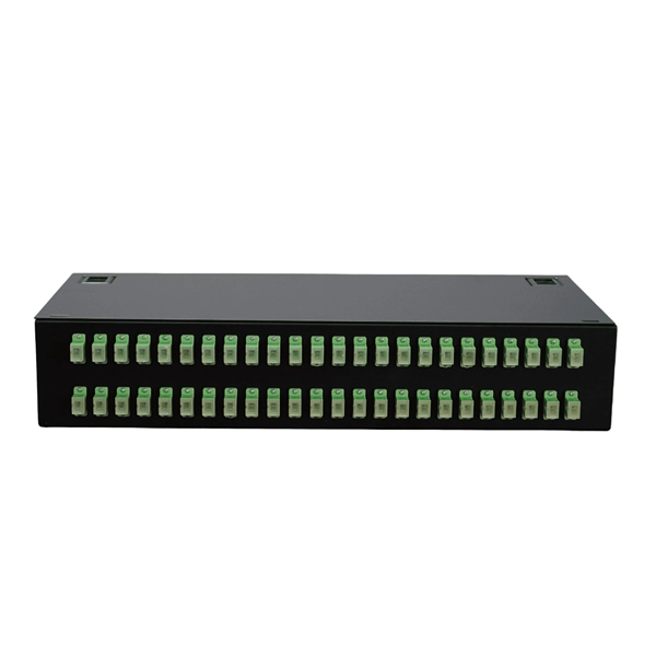
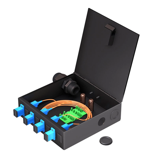
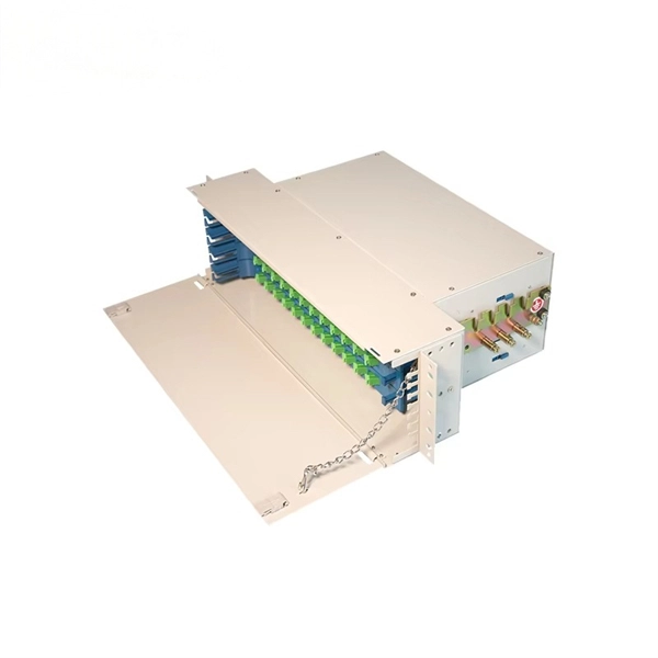
Telecom Fiber Optic Cable Drop Box
A Fiber Optic Termination Box is designed to secure and organize fiber optic connections, typically by linking fiber cables to an optical device through a patch cable. It can also function as a fiber optic distribu.
-
Fiber optic cable connected to router then connected to switch
If using a network switch with SFP ports, insert the fiber optic transceiver into the SFP port and connect the fiber optic cable to the transceiver. Connect the other end of the Ethernet cable to your network device, such as a computer, router, or. Fiber Optic Transceiver: Often used with media converters or network switches, these devices convert electrical signals to optical signals and vice versa. Patch Panel. As we speak I just have optic fibre (Community Fibre) connected to my Huawei modem / Linksys Velop which will be connected to a new POE switch (need to identify the best model to be compatible with my optic fibre extension project). Network topology refers to the way in which the links and nodes of a network are arranged in relation to each other. Use a standard Ethernet cable (Cat5e/Cat6) to.
[PDF Version]
-

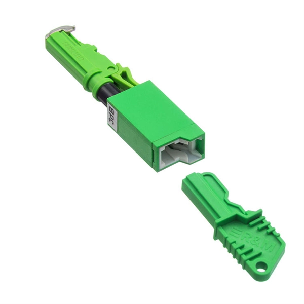
Single-mode port connected to multimode fiber optic cable
Single mode and multimode fiber cables are quite different when it comes to size, light source, signal, and so on. So, they definitely are not interchangeable, and compatibility issues can occur when you try to connect a single mode fiber optic connector to a multimode network. This is where fiber conversion comes in. Single-mode. To realize the short-range direct connection to the end B switch with the same port, the same 10GBASE-SR SFP+ module should be plugged into the end B switch port. What if end B is located in. It's possible because Multi-mode optical cables have a very wide fiber core – 62. Understanding the key differences between these two technologies is essential for IT professionals, business owners, and even homeowners looking to future-proof their network.