-
Multimode optical cable test length requirements
The cable should be longer than either of the following specifications, Event Dead Zone or Loss Dead Zone and the pulse length being used. Corning recommends that all fiber optic systems be tested to a minimum set of standards. So, you drop everything and i vestigate. He's right – it is n t working. Link testing of multimode segments should be done with an 850/1300nm dual wavelength unit. Since there is not an IEC/EIA. The length of launch cable used can very depending on the measurement needs. NEIS® are intended to be referenced in contrac documents for electrical construction ation or liability to users of this publication. Existence of a standard shall not preclude any member or nonmember of NECA or FOA from specifying or using. Other than for short-reach single-mode applications that are more susceptible to reflections and take connector reflectance into consideration, insertion loss testing, length, and polarity are really all you need for Tier 1 certification testing. Measured in decibels (dB), insertion loss is the. ANSI/TIA‑568.
[PDF Version]
-
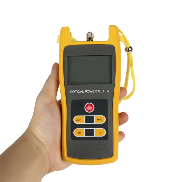
How to test the continuity of a multimode fiber optic cable
The three standard methods for testing fiber optic cabling are a visible light source, power meter and light source, and optical time domain reflectometer (OTDR). Fiber optic testing for continuity is crucial in ensuring that light transmits through fiber optic cables without interruptions, safeguarding seamless data transmission. As the components like fiber, connectors, splices, LED or laser sources, detectors and receivers are being developed, testing confirms their performance specifications and helps. Fiber optic testing ensures the performance and reliability of fiber optic networks. It helps minimize downtime, reduce maintenance costs, and support system upgrades or reconfigurations. If it's a long outside plant cable with intermediate splices, you will probably want to verify the individual splices with an OTDR also, since that's the only way to make.
[PDF Version]
-
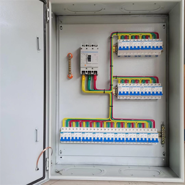
How to check optical loss on a Huijue switch
Execute the command, display transceiver [ interface interface-type interface-number | slot-id ] [ verbose ] to check the optical module information on the device interface. During use, reading optical module information helps understand its real-time operating status, enabling faster troubleshooting of link abnormalities. The following uses the. Here is an example on how to query or display optical power of an interface in a Huawei Router. from transceivers Check “Alarm information” section for warnings, LOS Alarm means no inbound signal, execute display this to check shutdown mode, execute undo shutdown if necessary. Execute the command, display.
-
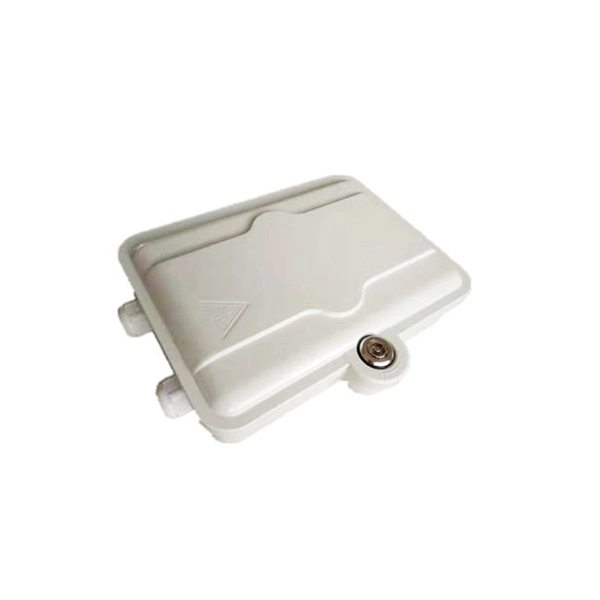
Telecom Splitter Loss
Calculate insertion loss for passive optical splitters in PON and distribution networks. Power is divided equally among output ports. Excess loss accounts for manufacturing imperfections, typically 0. A deeper understanding of these. Use 2×N when two inputs feed the same distribution stage. Common values: 2, 4, 8, 16, 32, 64. 5 dB depending on splitter type. By dividing a single optical signal from a central Optical Line Terminal (OLT) into multiple outputs for Optical Network. It is an optical fiber tandem device with many input and output terminals, especially applicable to a passive optical network (EPON, GPON, BPON, FTTX, FTTH etc. ) to connect the MDF and the terminal equipment and to branch the optical signal.
-
What is the loss of a 12-channel splitter
A splitter will have approximately 3. The theoretical loss assumes perfect splitting with no imperfections. In practice, losses are slightly higher due to: Insertion loss tells you how much weaker the signal becomes after passing through the splitter. Let's say you have a laser output at 0 dBm (which is 1 milliwatt of optical power). If you experience signal issues while using a splitter, you may need to install a distribution amplifier or a preamplifier. For example, for the loss (attenuation) in a segment of optical fiber we have the value at the input of the segment and at its output.
-
How to measure the loss rate of a beam splitter
To accurately measure optical splitter loss, utilize optical test equipment like power meters and spectral analyzers. Here's how: Measure the optical power at both the input and output ports of the splitter. This loss is primarily quantified as insertion loss, which measures the reduction in signal power due to the splitter's presence in the optical path. Common values: 2, 4, 8, 16, 32, 64.
-
Fiber optic flange splicing loss
Poor Fiber Cleave: Angled or chipped cleaves prevent proper core alignment. Misalignment: Incorrect positioning of fibers leads to light leakage. Core vs Cladding Mismatch: Using different fiber types without adjustment. Fiber optic pigtails are used to connect fiber optic cables using fusion or mechanical splicing. What is a mechanical splice? What is a fusion splice? Why splice? Fiber splicing is one way to join two optical fibers together so the light energy from one optical fiber can be transferred to another. Typical splice loss values (the measure of loss in optical power across the splice point) are usually lower for fusion splices (typically less than 0. 1 dB) than for mechanical splices (around 0. This tool uses the Marcuse Gaussian Approximation to calculate losses from intrinsic mismatch and extrinsic alignment errors. The focus of this paper is ultra low loss splicing for telecommunications product assembly, with typical loss of <0.
[PDF Version]