-
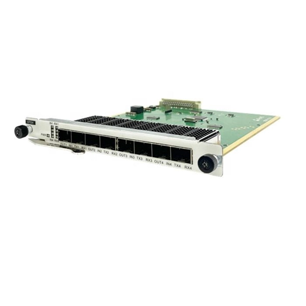
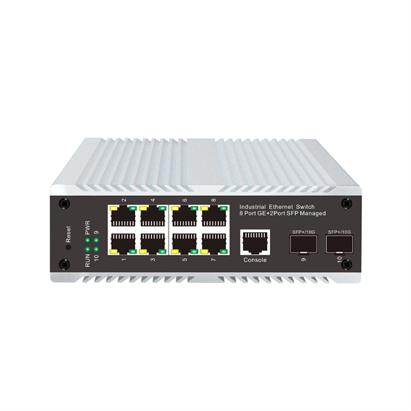
Optical modules are used in switches
Switch optical modules, which convert electrical signals to optical signals and vice – versa, and optical interfaces, which serve as the physical connection points, play a pivotal role in determining the speed, distance, and reliability of data transmission. Everything you need to build an optical network from end-to-end. Common optical module types such as SFP. SFP (Small Form-factor Pluggable) is a compact, hot-pluggable network interface module used to connect network devices (switches, routers, firewalls) to fiber optic or copper cables. Think of it as the “translator” for your network equipment, converting electrical signals into optical signals. Describes what an optical module is and FAQs, including the fundamentals, appearance and structure, key performance counters, common types, and naming conventions of optical modules, causes of optical module failures and corresponding protection measures, types of optical modules supported by. An optical transceiver module, often simply called an optical module, acts as a signal conversion interface in fiber optic networks.
[PDF Version]
-
Optical switches are cheaper than electrical switches
Optical: Optical switches can have a higher initial cost due to the technology involved. They're a core component in fiber-optic networks, where data travels as pulses of light through glass fibers. Every time that light needs to change direction or jump. Optical switching represents a fundamental technological evolution, shifting data routing from the domain of electrons to the realm of photons, or light. This transition allows data to remain in its native optical form as it travels through fiber optic networks, eliminating the need for. Dater centers (DCs), consisting of tens thousands of servers connected by large switching networks, provide the infrastructure for online applications and services such as cloud computing, social networks, file storage, and web search. So, what is the difference between optical transceivers and switches? What is the Difference Between Optical Transceivers and Switches? Optical transceiver is a very cost.
[PDF Version]
-
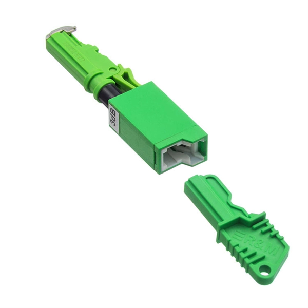
How to convert an electrical port to an optical port on a switch
A switch SFP port converts electrical signals into optical signals via SFP transceivers, or maintains them electrically for copper connections. By using an SFP to RJ45 adapter (e. 5G SFP), you can seamlessly connect legacy Ethernet devices to modern fiber-optic. The RJ45 port is a built-in electrical port of a Gigabit Ethernet switch, and it is mainly connected by Category 5, Category 5e, Category 6, and Category 6e twisted-pair cables. However, modern networks often combine both technologies. The good news: you can bridge them easily using the right hardware, such as media. An SFP port on a switch or router SFP port enables network engineers to connect multiple media types, from fiber optic links to copper Ethernet. An SFP transceiver acts as a compact, hot-swappable optical transceiver that.
-
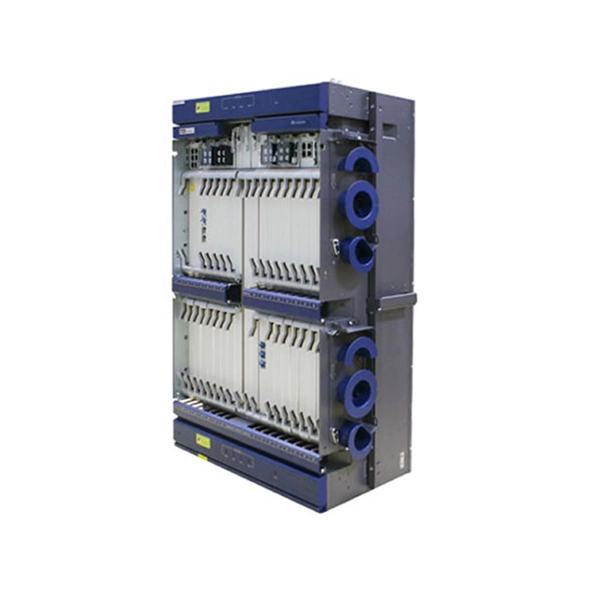
How is the serial interface of the XFP optical module
The XFP 2-wire serial interface is used for serial ID, digital diagnostics, and certain control functions. It was defined by an industry group in 2002, along with its interface to other electrical components, which is called XFI. XFP modules can be installed or replaced in an Extreme Networks switch, I/O module, or router without powering off the system. All Extreme Networks XFP modules comply with. This Juniper Networks® XFP-10G-S compatible XFP transceiver provides 10GBase-SR throughput up to 300m over multi-mode fiber (MMF) using a wavelength of 850nm via an LC connector. It can operate at temperatures between 0 and 70C. The transceiver is compliant with CPRI, eCPRI. With these features, this 10G SFP+. ID systems defined for the GBIC and SFP transceivers. 12 document apply to Beta-and Production-level units only. Physical Medium Dependent (PMD) sublayer and baseband medium, type 10GBASE-S (short wavelength serial), 10GBASE-L (long wavelength serial), and.
[PDF Version]
-

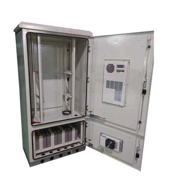
Is the H3C switch an optical port or an electrical port
H3C S1850V2-X switch series comes with standard Gigabit copper ports and Ten-Gigabit optical ports, making it a good fit for complex network environments and network expansion. H3C FS6300V2-EI series switches are a new generation of high-performance, high-port density, high-security Layer 3 Ethernet switches developed by H3C Technology Co. (hereinafter referred to as H3C) using industry-leading ASIC technology, supporting IPv4/IPV6 Dual-stack management and. A Combo port can operate as either an optical port or an electrical port. Inside the device there is only one forwarding interface. You can specify a Combo port to operate as an electrical port or an. This video provides a comprehensive guide on configuring and troubleshooting Combo ports on H3C Ethernet switches. Reasonable cable routing can improve efficiency by facilitating installation and removal of fan trays, and some other components. Interface cables are routed through the. Packaging Details:1. Rated voltage range: -48 ~ -60V DC.
[PDF Version]
-
The function of optical cable coiling
The coiling system must maintain balanced tension, consistent feed speed, and smooth direction transitions. The modern coiler uses a wire arrangement tool to ensure perfect layering—each loop sits exactly beside the previous one, maintaining the coil's structure. The modern fiber optic cable is the backbone of global communication networks, connecting continents through vast data highways. Today's automatic winding tools have. Fiber optic cable filling compound is not ordinary “grease” or “petroleum jelly,” but rather a semi-transparent paste-like functional material composed of base oils, thickening systems, water-blocking components, antioxidant systems, and other materials. The cable coiling and reserving device has a simple structure, offers convenient assembly and use, and can avoid accidental pull-out of a coiled and stored cable caused by. The CableCoiler 1300 is a standalone, fully synchronized high performance cable coiler for Schleuniger cut and strip machines. Often, coils are made with a.
[PDF Version]
-
Laying optical cables on the road
The document outlines steps like obtaining permissions, excavating trenches, laying ducts, providing additional protection, backfilling trenches, and performing optical tests after installation. This article gives an overview of this technology, which enables road-surface wiring by installing optical-fiber cables in grooves formed on asphalt pavement. Light signals traveling through a pure glass core offer significantly greater bandwidth and signal integrity, making it the preferred choice for connecting distant buildings. 4. FO-VC2 JOINT USE - VERICAL MIDSPAN CLEARANCES 48. RF W8P04C – cable. The Fiber Optic Association, Inc. (FOA) was founded in 1995 to help develop the workforce to build the fiber optic networks to support a rapid expansion in communications and the Internet. Before starting the installation, it is important to keep.
[PDF Version]
-
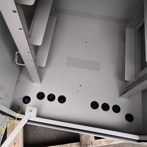
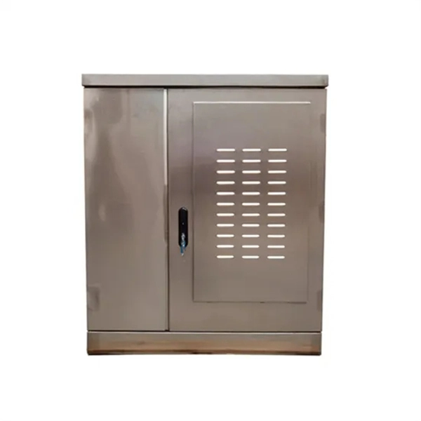
What are the main components of an optical distribution box
ODF, also known as optical distribution frame or fiber optic patch panel, is a critical device used in optical communication for managing and distributing optical fibers. They provide efficient fiber optic management, connectivity, and protection. It is usually a compact and structured framework composed of a steel shell and internal fiber splice tray as the main. This complete guide explores everything you need to know about ODFs — from their structure, types, and key components, to installation best practices and modern design trends. Whether you're building a central office, data center, or FTTx distribution network, understanding the right ODF.
-
Optical communication products specifically refer to
Modern communication relies on optical networking systems using optical fiber, optical amplifiers, lasers, switches, routers, and other related technologies. Optical communication, also known as optical telecommunication, is communication at a distance using light to carry information. It can be performed visually or by using electronic devices. The earliest basic forms of optical communication date back several millennia, while the earliest electrical. Therefore, NASA is developing optical communications to address limitations of radio frequency (RF) communications, including: bandwidth, spectrum and overall size of frequency packages and power used.
-
Underground Depth of Optical Cable
Fiber optic cables are typically buried between 12 and 36 inches (30–90 cm), depending on installation environment, soil conditions, and load requirements. In high-load areas such as roads or backbone routes, burial depth can reach 48 inches (120 cm) or more. With international fiber networks predicted to grow to over 1. 8 million km in scope by 2025 (per TeleGeography), burying these cords of light comes with the benefits of avoiding cable damage, decreasing downtime, and extending their operational lifetime. For broader context on underground. Underground cables are pulled in conduit that is buried underground, usually 1-1. 2 meters (3-4 feet) deep to reduce the likelihood of accidentally being dug up. In extreme cold climates, cables may need to be buried at greater depths where there temperatures are colder and frost penetrates to. Estimate minimum burial depth (cover) for underground electrical, fiber, and low-voltage cable runs using a practical, code-aware ruleset. Always consult local utility regulations and obtain necessary permits before excavation.
[PDF Version]
-
Hazards of Laying Optical Cables
Optical fibers, though renowned for their efficiency and bandwidth, aren't immune to risk factors that could spawn safety hazards. The very nature of fiber optic cabling requires handling microscopic strands that, when damaged, can cause signal loss or, worse, physical harm. Understanding the safety hazards that go with fiber optic cable is critical for those who install or maintain fiber optic systems. As electrical professionals, most of us take fiber optic (FO) safety for granted. Recognizing the potential safety hazard inherent in the installation and maintenance of optical fibers is crucial to mitigating risks of personal or property damage. Know the standards that apply to your work Whether you're installing new fiber optic cables or troubleshooting and repairing an existing fiber network, a working knowledge of the regulations that apply to your. However, fiber optics installation is not without risks. Even the output of OTDRs, WDM and fiber amplifier systems, which are. Working with fiber optic cabling requires precision, skill, and a strong understanding of cabling safety.
[PDF Version]