-

Phase Modulation Principle of Fiber Optic Sensors
Phase modulation occurs when an external physical parameter—such as strain, temperature, pressure, or acoustic waves —interacts with the optical fiber. This interaction alters the effective optical path length that the light travels. Optical phase-modulation technique is a very powerful tool used in a wide variety of high performance photonic systems. Fiber-optic sensors and gyroscopes, integrated-optics sensors, or high-performance photonic integrated circuits are some examples of photonic systems where the optical. The phase change is converted into an intensity change using interferometric schemes (Mach-Zehnder, Michelson, Fabry-Perot or Sagnac forms). What would be the output intensities and fringe visibility from both outputs? The Michelson interferometer. Access to the requested content is limited to institutions that have purchased or subscribe to SPIE eBooks. You are receiving this notice because your organization may not have SPIE eBooks access. * You currently do not have any folders to save your paper to! Create a new folder below.
[PDF Version]
-
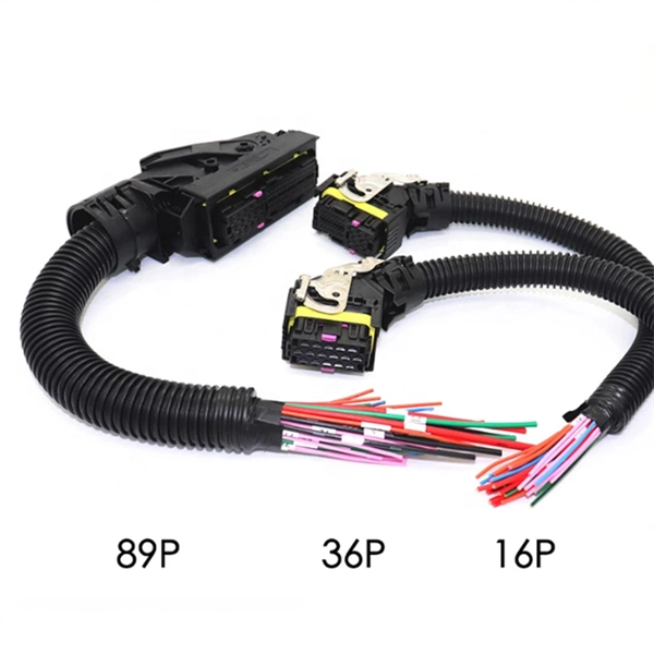
What are the techniques for splicing optical cables What are the prices
There are two main methods of splicing: mechanical splicing and fusion splicing. This blog will delve into the nuances of each method, comparing their costs, labor efficiency, network performance, and more, to help you decide which splicing technique is best suited for your. This is where fiber optic cable splicing—the process of creating a permanent, high-performance join between two fiber ends—becomes critical. At Turn-Key. Fiber optic splicing is the process of joining two fiber optic cables together so that light signals can pass with minimal loss or reflection. Splicing is typically required during cable installation, maintenance, or network expansion. 1dB for fusion) and degrade over time in outdoor environments.
-
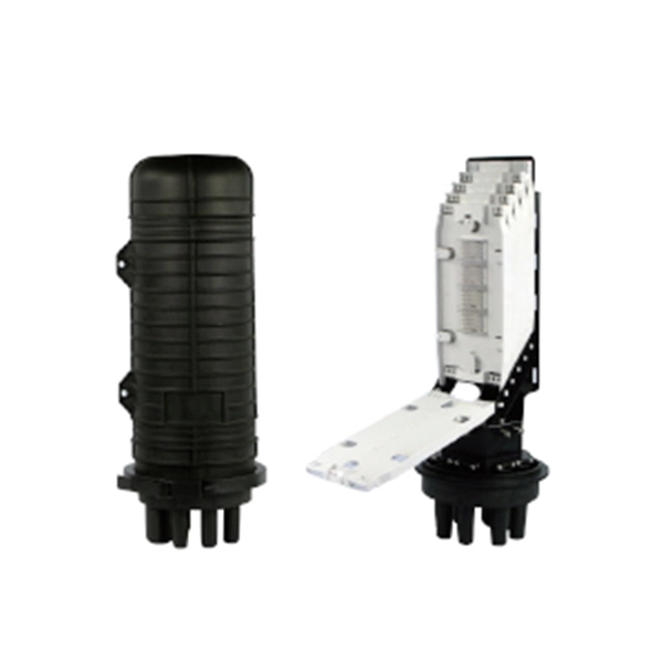
Fiber optic cable splicing techniques using heat shrink tubing
Carefully release each cable from splicer clamps. Slide shrink sleeve over exposed fiber and place in splicer's heating compartment; sleeve should cover each side roughly 3cm from joint. Consult the cable spec fication sheet for the cable you are installing. 1dB for fusion) and degrade over time in outdoor environments. A professional splice kit includes: Every splice starts with proper preparation: clean the work area, protect against wind, and. Single holed (preshrunk) ends eliminates improper fiber threading. Extended liner length prevents contact between the fiber and their backbone. Clear sleeve design permits easy centering. There are 7 procedures to perform in the splicing process; roughly in the following order: Procedures 2 and 3 will be performed twice; once for each of the two cables. Preparing to Use Heat Shrink Wrap: - Slide heat shrink wrap through one end of the fiber optic. A fiber optic heat shrink tube is used for reinforcing the splice connection.
[PDF Version]
-

Techniques for Calculating Relay Protection Settings
Use this Protection Relay Setting Calculator to calculate pickup current, time multiplier settings (TMS), operating time, coordination time interval (CTI), and plug setting multiplier (PSM) using fault current, CT ratio, and IEC 60255 curve parameters. For thermal overload protection (ANSI Device 49), the pickup is typically set at 115% to 125% of motor full-load amps depending on service factor. For overcurrent. This technical report refers to the electrical protections of all 132kV switchgear. All calculations are based on the available documentation/ information. These settings may be revaluated during the commissioning, according to actual and/or measured values. Presented at the 51st Annual Minnesota Power Systems Conference Saint Paul.