-

What does RF mean in optical transmitter
RF over Fiber (RFoF) refers to the technology that transmits radio frequency (RF) signals over optical fiber cables. RF to optical transmitters play a critical role in enabling high-speed data transfer over long distances using fiber optic technology. Main technical advantages of using fiber optical links are lower transmission losses and reduced sensitivity to noise and. RF over fiber (RFoF) is the method of converting a radio wave (RF) into light by modulating the intensity of the light source (typically a laser) with RF signal. This is an analog process and no digitization is used.
-
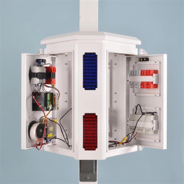
Distribution Box Ground Resistance Test
The selective testing method uses one clamp and two stakes. It allows you to measure the ground resistance at specific parts of an installation, isolating the system to check or reference what's in place. Th.
-
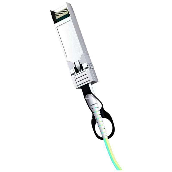
How does the optical module test group perform its tests
Optical modules will go through strict testing and quality inspection procedures before shipment, such as material testing, parameter testing, aging testing, real machine testing, end-face testing, etc. In fiber optic networks, optical transceivers such as SFP, SFP+, QSFP28, and QSFP-DD play a vital role in converting electrical signals into optical signals and vice versa. Testing these modules ensures performance, compatibility, and long-term reliability in bandwidth-intensive environments like. QSFPTEK suppliers have strict transceiver testing and quality control processes, and each optical module is delivered with a complete testing process. Optical modules can realize end-to-end signal transmission, and it performs optical communication through optical fibers. However, due to the architectural differences between 4-channel and.
[PDF Version]
-

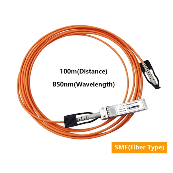
How to connect the fiber optic test patch cord
Just use the one-jumper reference method to set the reference and an adapter to connect the jumper to the test reference cord. You can put in a fibre patch cord at home. You just need to follow easy steps and be careful. Unfortunately, equipment cords are also. Correct patch-cord installation is essential for maintaining low insertion loss, stable return loss, and long-term reliability in both indoor and outdoor fiber networks. This guide addresses expert-certified best practices applied by professionals in the telecommunications, data. Watch as we demonstrate the testing process for 12-fiber MPO patch cords using a laser source. more Watch. In today's high-performance networks, fiber optic patch cables are the lifelines that ensure smooth data flow across switches, servers, and routers. Even the most advanced optical transceivers can only perform at their peak when paired with properly installed, clean, and precisely managed fiber.
[PDF Version]
-
Sd-wan device brands
Thanks to UCaaS, you have cloud services to consider when looking for an SD-WAN solution as well as on-site solutions in the form of appliances or software. We have put together a shortlist of the best SD-.
-

Optical module test power not adjusted too low
What does it mean if the transmitted power is too low? Low transmitted power can mean the connectors are dirty. Clean the connectors, check the module, and look at the fiber. If it still does not. Stable optical power is the foundation of every high-capacity optical transport system. Even minor deviations—whether too high, too low, or unstable—can impact signal integrity, trigger service alarms, or interrupt traffic on DWDM, OTN, or long-haul optical line systems. Because optical networks. The article Digital Diagnostic Function (DDM) For Optical Modules describes that DDM function can be used for real-time monitoring and fault location of the module's working status, in which the optical module's transmitting optical power and receiving optical power are the key parameters for. To test transmitted power in sfp optical modules, you use an optical power meter to get exact results. Many sfp modules also have DOM/DDM, which lets you see digital diagnostic monitoring data on network equipment. Built into modern SFP/SFP+/ SFP28 /QSFP family modules and standardized by SFF-8472, DDM/DOM exposes real-time values for the module's temperature, supply.
[PDF Version]
-
How to test a photovoltaic panel with a multimeter
Testing solar panels is easy with a multimeter! To test the current, simply connect the multimeter to the panel's output. Whether you're a seasoned solar enthusiast or a newcomer to the world of renewable energy, knowing how to use a multimeter to test your solar panels is a valuable skill that can empower you to take control of your energy production. Measure Voc (open circuit voltage) — if it reads 0V, the panel or wiring is dead. If Voc is normal but the system is not producing, the problem is downstream. Solar panels are usually tested under standard conditions using a light source that mimics the light from the sun on a clear day. This helps you spot issues early and keep your system running efficiently.
-
Latest Standards for Relay Protection Withstand Voltage Test
IEC 60255-5 is the standard that defines insulation coordination for these devices — the test voltages, impulse withstand levels, and minimum insulation resistance values that every protection relay must meet. This article breaks down the standard's requirements with the specific clause numbers and. Abstract: Design tests for relays and relay systems that relate to the immunity of this equipment to radiated electromagnetic interference from transceivers are specified in this standard. Two types of tests are specified: the oscillatory (SWC) and. IEEE Standard for Relays, Relay Systems, and Control Devices used for Protection and Control of Electric Power Apparatus--Surge Withstand Capability (SWC) and Electrical Fast Transient (EFT) Requirements and Tests Abstract: Design tests for relays, relay systems, and control devices used for.
[PDF Version]
-
Inspection after changing the setting value of the relay protection device
The purpose is to inspect the insulation between the relay terminals and the ground. Use a megohmmeter (such as 500V DC). Check wiring & . Protection Relay Testing is the procedure used to verify the performance, accuracy, timing, and operational condition of protective relays installed in electrical systems. These relays monitor electrical parameters such as current, voltage, frequency, impedance, and phase angle. But when it's needed, it has to perform. Servicing protective relays per manufacturer and NETA recommendations ensures they work properly to prevent injury or extensive damage to your plant during. Low Tension (LT) protection relays protect electrical systems by finding abnormal conditions such as Ground faults.
-
The cc08 program-controlled switch is a core network device
The CC08 switch is a high-performance electrical switching device designed for use in medium-voltage power distribution systems. Its robust construction and versatile specifications make it ideal for industrial and utility applications where reliability and efficiency are critical. These switches are designed to control the flow of electricity within a circuit, enabling users to turn devices on or off, select different operational modes, or manage complex. C&C08 B: Access product manuals, HedEx documents, product images and visio stencils. List of Explain the basic principle and structure of the C&C08 Switch system. The C&C08 is divided into 128-mode and 32-mode. The six flags in a TCP header are switches that can be set to on or off.