-
35kV busbar of the substation
This guide provides a detailed technical description, calculations, design considerations, and best practices for designing busbar systems in substations. Presented single line diagrams and layouts are generalized since they depend on the type and voltage (s) of the substations. 1 Accident Overview On March 17, 2023, a photovoltaic. Here, we provide an overview of common substation busbar configurations—Single Bus, Main and Transfer, Double Breaker/Double Bus, Ring Bus/Ring Main, and Breaker and a Half. The 35KV bus bar structure comprises a transformer A phase bus bar, a transformer B phase bus bar, a transformer C phase bus bar and a neutral conductor, wherein two. There are several Busbar Arrangements in Substations that can be used in a sub-station. The following are the important bus-bar arrangements used in.
-
The 10kV busbar has been changed from maintenance to operation
There are many standards on the subject pertaining to different voltage levels of switchgear, which normally defines four separate aspects of maintenance, with each new stage based on the preceding one, 1. Inspection, 2. Servicing, 3. Examination and 4. Overhaul. These are dealt with in detail below:Maintenance covers a wide range of activities, all of which are required to keep the switchgear in ready condition at all times to enable it perform its functions satisfactorily. The parts subjected to normal wear and agingneed to be serviced for ensuring full reliability of the operations. These parts may be mechanical components or electrical com. Safety features need to be planned before switchgear units are ordered. The requirement of locking off parts of the system (for carrying out maintenance work on the associated plant) should be finalised. Proper interlocking arrangements should be provided for this purpose. All metal-enclosed switchgears are designed so that all live conductors are.
[PDF Version]
-
Function of the small busbar in the central power switch
The bus bar is a metal strip that distributes electrical current to the individual circuit breakers. In most assemblies you will find horizontal main bars, vertical risers, neutral and equipment-ground buses, and purpose-designed. What are Busbars, Bus Stabs, Circuit Spaces, Breaker Slots, Neutral Terminals, and Ground Terminals in an Electrical Panel or Load Center? Electric panels and load centers in residential and commercial applications have some different setting for breaker installation ad load circuit distribution. They connect directly to the main power source and are designed to handle high current loads safely. Circuit Breakers act as protective devices within the panel.
-

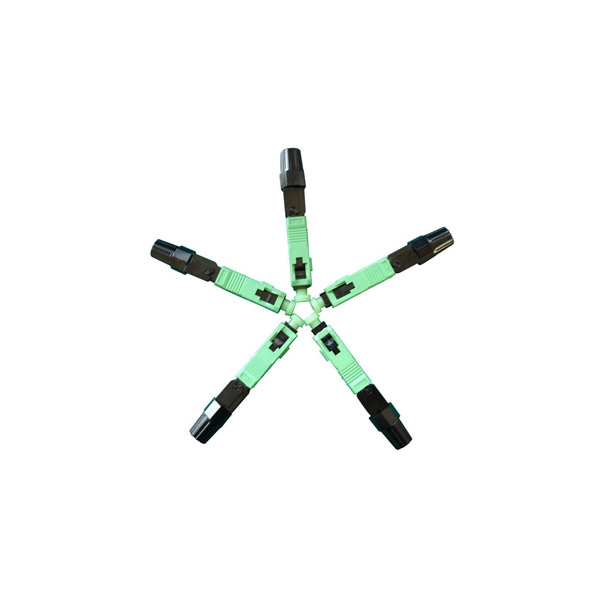
Busbar Connector Protection Box Usage
It is mainly used for insulation protection and safety protection of busbar connections in switchgear factories, power plants, and substations. In modern industrial electrical distribution systems, busbar systems serve as the backbone for power distribution, channeling electricity from main sources to various circuit protection devices and loads. The connection between molded case circuit breakers (MCCBs) and busbars represents a critical. The busbar joint protection box is made of radiation cross-linked polyolefin material. It has excellent physical, chemical and electrical properties. The high magnitude fault currents require high-speed. DEFINITIONS.
-
Small busbar acceptance standards and procedures
This article details the comprehensive standards for installing and inspecting busbars, including support brackets, insulators, and bus duct systems. You'll learn essential guidelines and. For complete safety instructions and precautions, always refer to the test equipment instruction manual. This approach is applicable to all types of metal enclosed busbar. Check for physical damage/defects. Check the bus arrangement to ensure that it is consistent with the approved plans. Compliance with recognized quality standards ensures electrical safety, reliability, and regulatory acceptance, especially for telecom, data centers, and industrial electrical applications. Buyers often. IEC 61439 is a standard developed by the International Electrotechnical Commission (IEC) that covers design verification for low-voltage electrical products and assemblies. Main keywords for this article are Bus Bars and Bus Ducts Design Requirements, ANSI C37.
[PDF Version]
-
Protection level of busbar connectors
The International Electrotechnical Commission (IEC) sets out standardized testing procedures and benchmarks to ensure that busbar contact resistance remains within safe and acceptable limits. IEC standards are developed through international consensus and are used globally. The integrity of busbar joints is critical because. Busbars in power systems are the location where transmission lines, generation sources, and distribution loads converge. Because of this convergence, short circuits located on or near the busbar tend to have very high magnitude currents. The high magnitude fault currents require high-speed. Industry data shows that loose or improperly torqued busbar connections account for a significant percentage of electrical panel failures. Busbar distribution ensures these requirements are fully met. Performance criteria of. DEFINITIONS.
[PDF Version]
-
Nordic Cable Tray and Busbar Manufacturer
We know cable management systems. Hilding Group consists of the three companies Nordic Wire Tray, Hiltec and Hilcon. Cable trays has an overall mission: to organize cables. In order to successfully meet the market's demands, high requirements and adaptations to various industries, a broad and well-thought-out range is required. Nordic Wire Tray's cable laying system consists of wire trays sold under the X-Tray. We specialize in manufacturing high-quality cable support systems. Our product range includes galvanized steel and acid-proof steel cable ladders, cable trays, wire mesh trays, lighting tracks, and aluminum-frame cable management systems, socket poles, and the unipro® lighting track system. Material Hybridization: Combinations of powder-coated metal, stainless steel, and solid wood or MDF are prevalent. New name, new look, same Nordic quality We continue to drive innovation in cable. Our cable management systems are designed to withstand the toughest conditions in C5-M environments, while delivering cost-effective and flexible solutions for platforms, vessels, and ports.
[PDF Version]
-
How to ground the busbar of the switchgear
Bus bar grounding can be achieved by one of two methods: grounding clamps applied to bus bars or a separate switchgear section with a switching mechanism dedicated to ground. In most assemblies you will find horizontal main bars, vertical risers, neutral and equipment-ground buses, and purpose-designed. The purpose of this manual is to assist the user in developing safe and eficient procedures for the installation, maintenance and operation of the equipment. For additional information, refer to NEMA Standards Publication PB2. Dive in to power up your knowledge! These guidelines govern the busbar processing and installation procedures. With the exception of SF6-to-air bushings terminals, all active portions of gas-insulated switchgear (GIS) are contained within grounded enclosures, which means that they are not susceptible to inadvertent contact. This makes gas-insulated switchgear intrinsically safe. In addition, numerous. New Approaches for Maintenance Grounding in Medium-Voltage Switchgear by Joe Richard and David Mabius Executive summary Maintenance grounding has traditionally been performed by maintenance personnel working in close proximity to open switchgear.
[PDF Version]
-
The function of the small busbar in the switch cabinet
A busbar is a metal bar, usually made of copper or aluminum, that carries electricity inside switchgear. It connects the incoming power to circuit breakers and outgoing circuits, helping power flow smoothly and evenly. Good busbar design helps prevent overheating and electrical. Busbars are the backbone of a low-voltage switchboard: rigid conductors that collect and distribute current safely between incoming devices and outgoing feeders. It connects. The use of busbar systems with their versatile rail-adaptable connection, switching and installation devices is an ideal and cost-effective electrotechnical enhancement of modern distribution boards thanks to their small footprint, modular design and quick assembly contacts. Small Busbar Room (Top of the Cabinet): Houses busbars that distribute electrical power to different sections.
[PDF Version]