-
Relay protection panel reset
Operate the mechanical reset lever or pushbutton on the lockout relay, or use the relay's HMI/SCADA interface for electronic relays. For microprocessor relays, use the front panel or remote interface to acknowledge and reset the lockout/trip condition. In this comprehensive guide, we will delve into the essential steps for resetting a relay efficiently and effectively. From troubleshooting common issues to performing the reset process step-by-step. How can I reset the Alarm or Trip on 857 Motor protection relay? There are two status indicators named "Alarm" and "Trip" on the front panel that is mapped within the Output Matrix. #relay #lockoutrelay #electrical #howtoresetrelay #86relay #mastertriprelay lockout relay function lockout relay wiring diagram lockout relay 86 protection lockout relay wiring lockout relay operation lockout relay 86. View all of Eaton's protective relays PowerPort-E can not connect to the device. The settings in a 751 shouldn't be reset because of a loss of power.
[PDF Version]
-
Where are relay protection components located
First part is the primary winding of a current transformer (CT) which is connected in series with the line to be protected. The relays are in round glass cases. In electrical engineering, a protective relay is a relay device designed to trip a circuit breaker when a fault is detected. It emphasizes selectivity, coordination, fault response, and system behavior rather than individual relay devices. Relay protection is often misunderstood as a. A protection relay is a crucial component of electrical systems that safeguard infrastructure, employees, and equipment from electric problems and malfunctions. These relays are self-contained & compact devices that detect abnormal conditions occurring within the electrical circuits by measuring the. Operating Principles and Relay Construction: Electromagnetic relays, thermal relays, static relays, microprocessor based protective relays Time-current characteristics, current setting, over current protective schemes, directional relay, protection of parallel feeders, protection of ring mains.
[PDF Version]
-
Fire safety requirements for relay protection compartments
In order to effectively resist the effects of fire, heat, and smoke, a fire-rated barrier must be complete and whole. There cannot be any openings or holes in the wall such as open doors, windows, or holes f.
-
Steps for Short Circuit Calculation in Relay Protection
Voltage levels, transformer ratings and impedances, line lengths and impedances, generator/motor data. Select fault location Choose busbars or nodes where faults will be studied. Apply IEC. A short circuit occurs when an unintended low-impedance path forms between: Physical Causes: Critical Applications: ⚠️ Safety Critical: Incorrect fault current calculations can result in explosive equipment failures, arc flash incidents causing severe burns, and system-wide cascading failures. The principle is to grade the operating times of the relays in such a way that. The scope of study involves calculating the settings for protective relays to achieve selectivity during faults ocurring in the electrical network for the 13. In OC relays the coordination is based on the relay time-current characteristics of instantaneous and/or time delay units. Instantaneous units should be set so they. As of this update, Service Disconnect Switches, Surge Protective Devices, Switchboards, Switchgear, and Panelboards, Industrial Control Panels, Motor Controllers, Elevators, Industrial Machinery, and Transfer Equipment are all required to have short-circuit current ratings.
[PDF Version]
-

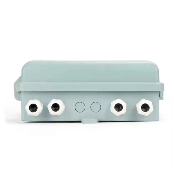
Busbar Connector Protection Box Usage
It is mainly used for insulation protection and safety protection of busbar connections in switchgear factories, power plants, and substations. In modern industrial electrical distribution systems, busbar systems serve as the backbone for power distribution, channeling electricity from main sources to various circuit protection devices and loads. The connection between molded case circuit breakers (MCCBs) and busbars represents a critical. The busbar joint protection box is made of radiation cross-linked polyolefin material. It has excellent physical, chemical and electrical properties. The high magnitude fault currents require high-speed. DEFINITIONS.
-
Internal relays of relay protection devices
The fault can be located upstream or downstream of the relay's location, allowing appropriate protective devices to be operated inside or outside of the zone of protection.OverviewIn, a protective relay is a device designed to trip a when a is detected. The first protective relays were electromagnetic devices, relying on coils operating on moving par. Electromechanical protective relays operate by either, or. Unlike switching type electromechanical with fixed and usually ill-defined operating voltage thresholds. Electromechanical relays can be classified into several different types as follows: "Armature"-type relays have a pivoted lever supported on a hinge or knife-edge pivot, which carries a moving contact. These relays may.
-
Price quote for relay protection testers in Iran
Best online prices for Fluke T+ and T+ PRO Electrical Testers with wide range of Fluke Electrical Testers. Shipping at door with custom and duty included in price quote. According to Volza's Relay Protection Import analytics, 24 verified Relay Protection buyers in Iran have imported Shipments from 19 global suppliers. PARS TABLEAU SANAT followed with 17% (4 shipments). DANESH ENERGY SARIR. Software Specifications, Capable of Testing Circuit Breakers (CB) and Sectioners, Capable of Testing Voltage Transformers and Capacitor Voltage Transformers (VT/CVT), Capable of Testing Voltage Power Transformers, Capable of Testing Current Transformers (CT). Capable of Testing Circuit Breakers. A relay tester is a specialized electrical testing instrument used to assess the performance, response time, accuracy, and operational integrity of protective and control relays in power systems and industrial automation. More than 20,000 relay test kits has been supplied to users in China and other countries, including 6-phase, 3-phase, single.
[PDF Version]
-
Which majors study relay protection
The most common majors for this role are Electrical Engineering, Industrial Technology, Electrical Engineering Technology, Biology, and Electrical/Electronics Maintenance And Repair Technology. This certificate provides engineers with a concentrated focus on power system protection and relaying. Notable schools that offer programs relevant to this field include California State University - Long. PROT 401 provides an overview of the principles and schemes for protecting power lines, transformers, buses, generators, and motors. It also reviews basic power system concepts and describes instrument. Protective relay technicians are the guardians of our electrical grids, ensuring power flows reliably and safely by installing, testing, and maintaining the critical devices that detect and isolate faults. In most cases, the material is.
[PDF Version]
-
What is the pressure plate of a relay protection device
Electromechanical protective relays at a hydroelectric generating plant. The relays are in round glass cases. The rectangular devices are test connection blocks, used for testing and isolation of instrument transformer circuits.OverviewIn, a protective relay is a device designed to trip a when a is detected. The first protective relays were electromagnetic devices, relying on coils operating on moving par. Electromechanical protective relays operate by either, or. Unlike switching type electromechanical with fixed and usually ill-defined operating voltage thresholds. Electromechanical relays can be classified into several different types as follows: "Armature"-type relays have a pivoted lever supported on a hinge or knife-edge pivot, which carries a moving contact. These relays may.