-

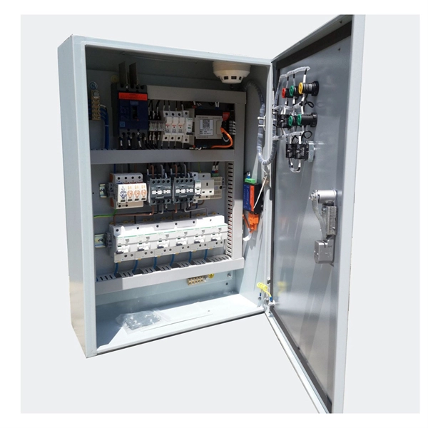
Functions and Applications of Relay Protection Cabinets
Protection relay cabinets are used to protect electrical power systems from damage caused by overloads, short circuits, and other abnormal conditions. Based on Operating Principle Electromechanical Relays: Work using moving parts and electromagnetic forces (traditional. Selectivity is a mandatory requirement for all protection, but the importance of it depends on the application. We work with plant operators, utilities, OEMs, EPCs, Data Centers and integrators to engineer panels that meet strict performance, safety, and compliance expectations. They are typically designed to detect and respond to these types of faults quickly and effectively, preventing any potential harm to people or.
-

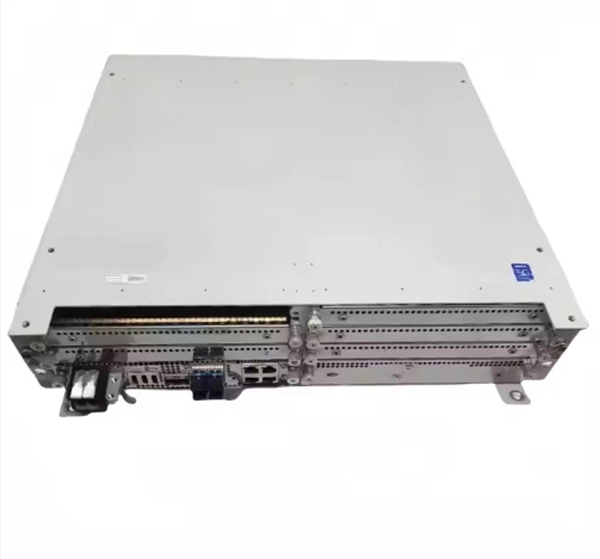
Circuit Breaker Relay Protection Equipment Model
Microprocessor-based solid-state digital protection relays now emulate the original devices, as well as providing types of protection and supervision impractical with electromechanical relays.OverviewIn, a protective relay is a device designed to trip a when a is detected. The first protective relays were electromagnetic devices, relying on coils operating on moving par. Electromechanical protective relays operate by either, or. Unlike switching type electromechanical with fixed and usually ill-defined operating voltage thresholds. Electromechanical relays can be classified into several different types as follows: "Armature"-type relays have a pivoted lever supported on a hinge or knife-edge pivot, which carries a moving contact. These relays may.
-
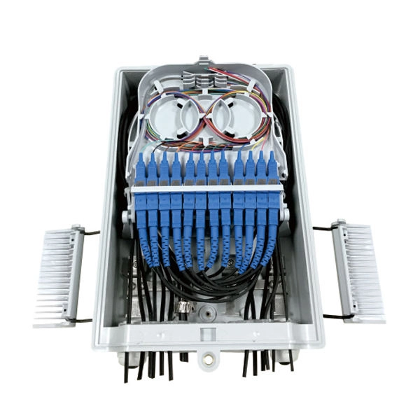
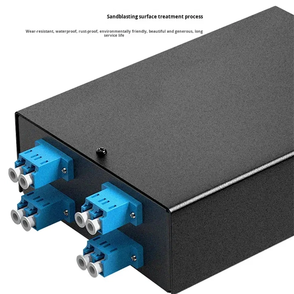
Wired Channel for Relay Protection
With the addition of a line tuner, the CCVT (used for potential input to the protective relay) can be used to couple the PLC signal to the power line. Protection systems are used to isolate faulted parts of the system, protect the electric system from instability, and minimize equipment damage. Directional distance and overcurrent schemes, interfaced with communication equipment, send and receive logic-based information between relay te minals to determine if the fault is external or internal to the. Important benefits include limiting tripping to faulted line section, high-speed simultaneous clearing for all internal line faults, preventing overtripping on external faults, and reducing transmission line and station damage. Applications of the concepts to accepted transmission line-protection schemes are also presented.
-
Requirements for Relay Protection Design
The IEEE standard for protection relays refers to a collection of guidelines developed by the Institute of Electrical and Electronics Engineers. This document provides recommendations, background and philosophy on relay protection that is not available in M07. They are intended to quickly identify a fault and isolate it so the balance of the system continue to run under normal conditions. For professionals working in utilities, industries, or renewable energy systems, understanding these standards is not optional—it is essential. This handbook covers the code of practice in protection circuitry including standard lead and device numbers, mode of connections at terminal strips, colour codes in multicore cables, dos and donts in execution.
-
Relay protection function of the main switch
A protective relay is an automatic device that detects abnormalities in an electrical circuit and closes its contacts. This action completes the circuit breaker 's trip coil circuit, causing the breaker to trip and disconnect the faulty section from the healthy circuit. First, relays were used as signal repeaters within long-distance. Fingrid's application guideline for relay protection presents the operating principles of the relay protection in Fingrid's 110, 220 and 400 kV power networks and the requirements for operation of the protection systems of Fingrid customers (hereinafter referred to as 'customer'). The application. Provides protection, logic, and metering All-in-one solution. Three fundamental components required for each circuit breaker. While this is bad, It's not a.
-
Is it dangerous to repair relay protection
Doing so may result in reducing Relay performance for insulation failure, contact welding, and contact faults, and might even result in burning or other damage to the Relay itself. Do not drop the Relay or dismantle it. Refer to the Safety Precautions for individual Relays for precautions specific to each Relay. Electric shock may. A relay that is correctly set for yesterday's system may become a serious risk after a plant expansion or load change. This article breaks down the most common protection relay misconfigurations in industrial facilities, why they happen, and how they impact system reliability and operational. onding to faults, ensuring the reliability and stability of the grid. However, unauthorised changes to protection relay settings pose a significant threat to the integrity of power systems. Although failure of a protective relay system may have severe local or regional impacts, most protective relay systems are not required to operate to prove they are in working order.
[PDF Version]
-
Relay Protection Inspection and Acceptance
This guide explores the different types of protection relays and their testing procedures, with a focus on tools like secondary injection test sets and three-phase relay test sets. To properly test relays, understanding their classification by design and application is. The testing and verification of relay protection devices can be divided into four groups: Type tests are needed to prove that a protection relay meets the claimed specification and follows all relevant standards. These are not repeated unless incorrect operation occurs. Although failure of a protective relay system may have severe local or regional impacts, most protective relay systems are not required to operate to prove they are in working order.
-

Relay Protection Test Wiring Method
One approach to test the total protection system is to use primary injection techniques (see appendix H) that trigger protective relays and lockout relay, trip circuit breakers, and initiate annunciations and indications. If applicable, documentation is required detailing how verified protection segments overlap to ensure there is not a gap. The purpose of this Standard Work Practice (SWP) is to standardise and describe the method for testing of Ergon Energy protection relays for commissioning purposes. This SWP should be interpreted in conjunction with Standard for Substation Protection (V1. From a technician's perspective, master the unique skill of testing protection. When the transformer wiring type is Y/Y (Y0), the test wiring is very simple: when testing phase A, the tester IA is connected to the phase A of the high voltage side, and the tester IB is connected to the phase a of the low voltage side. After the neutral line of the high and low voltage sides is. Function: Use electronic components like transistors to perform switching. Applications: Frequency, undervoltage, and overcurrent protection.
[PDF Version]
-
Several characteristics of relay protection are
To provide effective and reliable protection to the power system, a protective relay must have the following essential functional characteristics: Selective, Fast, Stable, Reliability, Sensitivity, Simple Construction and Installation Mechanism, and Cost-effective. A protective relay is an electrical switch which can automatically operate when a fault or any other abnormal conditions occur in the electrical system. It sends a signal to turn on the alarm or indicator or trip a circuit breaker to separate the faulty part from the healthy section. : 4 The first protective relays were electromagnetic devices, relying on coils operating on moving parts to provide detection of abnormal operating conditions such as. A protective relay is an intelligent electrical device designed to detect faults in power systems and initiate corrective actions such as tripping a circuit breaker. PSM – Plug Setting Multiplier (Current Setting Multiplier) What is PSM? 2).
[PDF Version]
-

Calculation of State Grid Relay Protection
Use this Protection Relay Setting Calculator to calculate pickup current, time multiplier settings (TMS), operating time, coordination time interval (CTI), and plug setting multiplier (PSM) using fault current, CT ratio, and IEC 60255 curve parameters. To adapt the grid to the requirements of intelligentization and the dispatching and control cloud technology route, this paper proposes a relay protection setting calculation method for power grid based on distributed parallel computing. These calculations are critical in industrial. The selected protection principle affects the operating speed of the protection, which has a significant im-pact on the harm caused by short circuits. The faster the protection operates, the smaller the resulting ha-zards, damage and the thermal stress will be.
-
Intermediate relays are commonly used in relay protection
Intermediate relay: used in relay protection and automatic control systems to increase the number and capacity of contacts. Its main function in an electrical control system is to carry. What is an Intermediate Relay? The intermediate relay is a low-power device for activating higher-power circuits. We can also call it an interposing relay. Depending on the application—whether for signal amplification, overload protection, safety shutdown, or high-frequency switching —different types of relays are used.
-
Career prospects for relay protection workers
Career advancement opportunities include roles such as protection engineer, system protection coordinator, or electrical project manager, often requiring certifications in relay technology and power systems. The Bureau of Labor Statistics projects nearly 25,000 relay and substation technicians will be employed by 2034 — steady demand that translates into thousands of openings each year as older workers retire. That means thousands of openings across the country. Jobs that don't require a four-year. The Fire Alarm Technician must be able to take lead in the service and inspection of fire alarm, door locking, and access control systems. They utilize advanced diagnostic tools and relay testing equipment to ensure the accurate operation of protective relays. As a Protective Relay Instructor you will cover the purpose, theory of operation, components, function, and testing/calibration/routine maintenance of electro-. Candidate must have experience with Electrical industrial maintenance as a field service engineer/representative/technician, electrician.
[PDF Version]