-
How to transmit optical fiber over long distances
The core of a fiber optic cable is surrounded by a cladding, which reflects light back into the core, allowing it to travel over long distances with minimal loss. We live in a hyper-connected world where a video call with someone 10,000 miles away feels seamless. But how does light travel across oceans and continents with. Fiber-optic cables revolutionize long-distance data transmission using light, outperforming copper cables significantly. This exploration examines their workings, efficiency principles, and modern applications. Attenuation is the progressive loss of signal strength that occurs as light travels through the fiber. The greater the distance, the greater. The process of data transmission over optical fiber involves a series of conversions between electrical signals and optical signals: Signal Encoding: The initial digital data, typically represented as electrical pulses, undergoes encoding to optimize it for optical transmission.
[PDF Version]
-

How to straighten a long optical cable
While a cut or damaged fiber optic cable can temporarily take your network down, it is possible to quickly fix the cable with the right tools. This wikiHow article will teach you how to splice a cut fiber optic cable back together with a fiber optic stripper and cutter and a fiber. In this video I'll show you How to Remove Kinks From Cables and straighten your cable again. To make the tangled, twisted cables or cord straight again you can use a few method. This will relax the cables and making. James Hornof is a Master Electrician and the Owner and President of B & W Electric based in Denver, Colorado. With over two decades of experience in the electrical construction industry, James specializes in field installation, management, estimating, and design. For this to happen, there needs to be some form of heat.
-
Applications of Passive Optical Networking Technology
A passive optical network is a type of telecommunications network that uses fiber optic cable to transmit data. It's also lightning quick, which is why a PON is the go-to for high-bandwidth content like high-speed internet service, streaming video, or handling voice over internet protocol (VoIP). They do not need powered devices. PON architecture lets one fiber help many users. It also makes installation easier. PON primarily utilizes a point-to-multipoint topology and fiber optical splitters to transmit data from a single point of transmission to multiple user. A Passive Optical Network (PON) is a high-speed, fiber-optic network architecture that delivers broadband internet access to multiple users without requiring active electrical components between the central office and the user's premises.
-
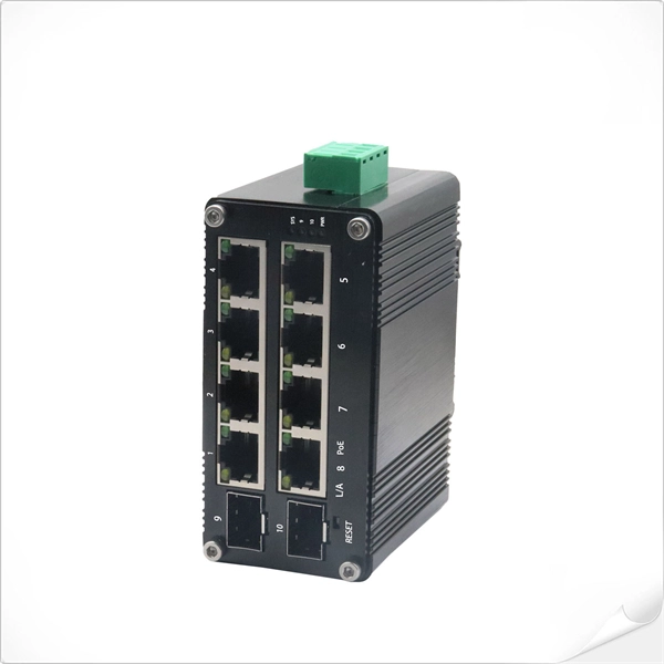
All-optical networking using optical switches
An all-optical Ethernet switch is a network switch whose service ports are entirely optical, meaning every interface uses fiber rather than copper. This design enables end-to-end optical signal transmission, avoiding the conversion between electrical and optical signals at the. Against this backdrop, all-optical Ethernet switches have emerged as a key solution that enables pure fiber-based networking with higher performance and future-ready scalability. Expressed in terms of analog bandwidth, a 1nm waveband translates to a bandwidth of 178GHz at 1300nm and. This paper first summarizes the topologies and traffic characteristics in data centers and analyzes the reasons and importance of moving to optical switching. They can function as core, aggregation, and access devices on campus networks and connect to upstream and downstream devices. ring numer-ous "optical to electrical to optical" (OEO) conversions. Transport is done with static point-to- oint optical links, while swi e connection-oriented data streams from input to output connections. Recent developments in all-optical circuit switching in combination.
[PDF Version]
-

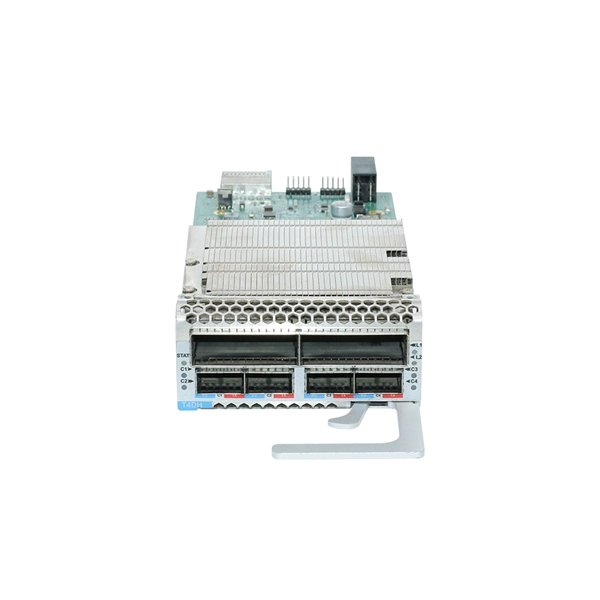
Selection Guide for QSFP Active Optical Modules for Cloud Computing
This QSFP module guide delivers a technical deep dive into the most prevalent QSFP transceivers, their specs, real-world deployments, and practical buying advice. Whether you're upgrading to 100G or optimizing your 40G links, this article is tailored for network architects, engineers, and system. The Ultimate Guide to QSFP Optical Modules: 40G to 800G Interconnect Evolution In today's digital era sweeping across the globe, data centers—the core hubs of information processing—have an insatiable demand for high-speed, high-density data transmission solutions. By increasing channel density, it enables higher port utilization and seamless upgrades on existing infrastructure. As a core component of high-speed networks, QSFP-DD. As high-speed networks continue to evolve, optical transceivers like QSFP-DD, QSFP28, QSFP56, SFP56, and SFP28 have become the core components enabling scalable and efficient connectivity across data centers and telecom environments. Below is a detailed breakdown of each module series.
[PDF Version]
-
Method for bundling optical cables
Fiber optic splicing is often the preferred way to connect two fiber optic cables because it has lower light loss (attenuation) and back reflection than connectorization. Fusion splicing and mechanical splicing are the two most common methods of fiber optic splicing. AOCsarrive. This document describes the specifications for preparing, routing, and bundling cables and attaching labels to these cables. Another method of connecting optical fibers is termination or connectorization, which consists of processing the end of a fiber optic bundle so that it can be connected to other fibers or devices through fiber optic. In the rapidly evolving fields of telecommunications, medical imaging, and industrial sensing, fiber optic bundles serve as the cornerstone for efficient and reliable data transmission.
-
Same optical splitter same account
Yes, with the optical splitter, various end users can access broadband networks through the same fiber. This point-to-multipoint architecture helps reduce space occupation and effectively save optical cable resources, achieving efficient network expansion at a lower cost. By dividing a single optical signal from a central Optical Line Terminal (OLT) into multiple outputs for Optical Network. A fiber optic splitter is a passive device that divides an optical signal into multiple parts. These devices help you control light signals well. This guide will demystify this pivotal passive device, exploring its types, working principles. A passive device used to split or combine signals on fiber optics may be called a splitter, combiner or coupler, but splitter is the most common term.
-
Main protective measures for optical cables
Maintain accurate as-built drawings and GPS coordinates for all buried cable routes. This prevents accidental cuts during future excavation. Cable protection extends beyond the fiber itself—connectors, splices, and enclosures must be safeguarded from environmental and mechanical. Fiber optic cables enable high-speed, long-distance data transfer, forming the backbone of modern communication. This guide covers how to. es conform to the guidelines expressed in the American National Standards Institute document (ANSI Z535) for hazard alert messages. Alerts are included in this instru d ath or serious i jury ectacles) conforming to ANSI Z87, for eye protection from accidental injury wh n ha dling chemicals, cab. Improper use of the connector end face on pigtailed fibers, e. Use of inferior quality fiber optic connectors. ESD damage is a major issue that can degrade the. It is important for fiber optic technicians to follow safety practices to avoid injuries and accidents.
[PDF Version]
-

What does a 72-core optical cable look like
GYTA53 fiber cable consists of 250um fibers held in gel-filled PBT loose tubes, and wrapped around a phosphatized steel wire central strength member. A waterproof compound fills the loose tube, and the center of the cable core is a metal reinforced core. 72 core fiber optic cable should be selected by fiber standard, cable structure, jacket, tensile strength, installation route, drum length, testing, and quantity. single mode GYTA53 fiber optic cable and multimode. Fibertronics' Fiber Optic Distribution Cable is composed of high quality colored tight buffers, aramid yarn and a PVC outer jacket. Their small bend radius allows for fast installations and easy terminations within confined. Corning ribbon plenum cables are designed for use in plenum, riser and general purpose environments for intrabuilding backbone installations and for high-fiber-count data centers.
[PDF Version]