-
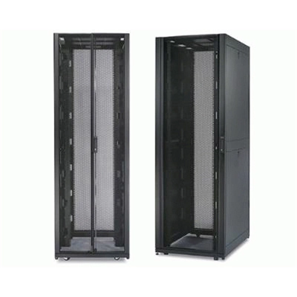
What is a fiber optic cable management rack also called
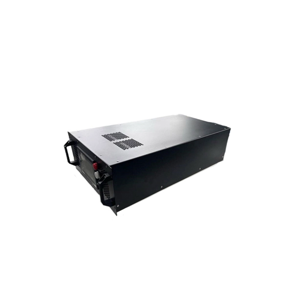
Also known as fiber optic enclosures or fiber entrance cabinets, these enclosures act as hubs where cables can be spliced, organized and routed through areas inside or outside a building. This article provides a clear technical view of cable management racks, their structures, and how to select the right solution for modern networks. It houses and protects fibre terminations, allowing you to manage high volumes of optical connections in a secure, scalable format. The Rack Mounted Optical Cable Terminal Box is a metal enclosure used for fiber cable. Fiber enclosures come in two primary types: wall mount and rack mount. On the other hand, rack-mount fiber enclosures are employed between or within. What Is a Fiber Patch Panel? A fiber patch panel is a mounted enclosure—either rack-mounted or wall-mounted—used to terminate, manage, and interconnect multiple fiber optic cables. Given its immense significance, it is essential for.
[PDF Version]
-
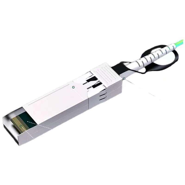
Fiber optic cable connected to router then connected to switch
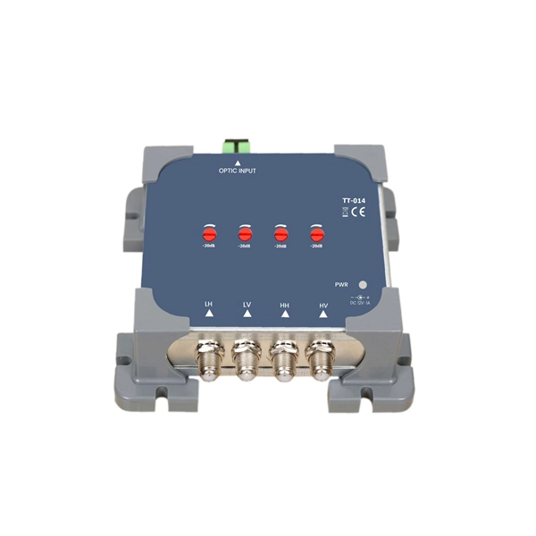
If using a network switch with SFP ports, insert the fiber optic transceiver into the SFP port and connect the fiber optic cable to the transceiver. Connect the other end of the Ethernet cable to your network device, such as a computer, router, or. Fiber Optic Transceiver: Often used with media converters or network switches, these devices convert electrical signals to optical signals and vice versa. Patch Panel. As we speak I just have optic fibre (Community Fibre) connected to my Huawei modem / Linksys Velop which will be connected to a new POE switch (need to identify the best model to be compatible with my optic fibre extension project). Network topology refers to the way in which the links and nodes of a network are arranged in relation to each other. Use a standard Ethernet cable (Cat5e/Cat6) to.
[PDF Version]
-
Optical cable channels are divided into
The light signal is divided into multiple channels with different frequencies and wavelengths, each transmitting a different data stream. In general, the fiber cable link system will be more secure if the fewer fiber cable segments. This region occupies a bandwidth of 95nm or 11THz! 8 cn cor where L is the fiber length, c is the speed of light, and ncor and nclad are the core and cladding refracitve indexes, respectively. Why not always use SMF? Optical phase information is lost in the detection process. What is a wavelength? What are optical wavelengths? What are nominal. In telecommunications, frequency-division multiplexing (FDM) is a technique by which the total bandwidth available in a communication medium is divided into a series of non-overlapping frequency bands, each of which is used to carry a separate signal. It essentially consists of a data transmitter, a transmission fiber (in some cases with built-in fiber amplifiers), and.
[PDF Version]
-

Single-mode port connected to multimode fiber optic cable
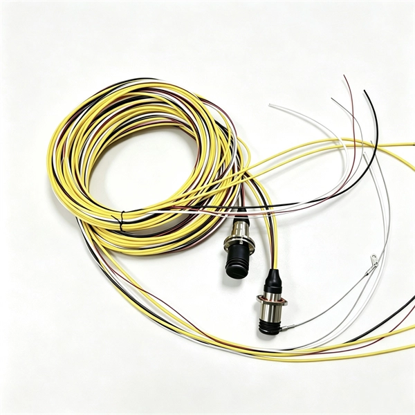
Single mode and multimode fiber cables are quite different when it comes to size, light source, signal, and so on. So, they definitely are not interchangeable, and compatibility issues can occur when you try to connect a single mode fiber optic connector to a multimode network. This is where fiber conversion comes in. Single-mode. To realize the short-range direct connection to the end B switch with the same port, the same 10GBASE-SR SFP+ module should be plugged into the end B switch port. What if end B is located in. It's possible because Multi-mode optical cables have a very wide fiber core – 62. Understanding the key differences between these two technologies is essential for IT professionals, business owners, and even homeowners looking to future-proof their network.
-
Translate the cable tray by 45 degrees
To create a 45-degree bend, cut the side rails to remove a segment calculated by the formula (Tan (22. Google's service, offered free of charge, instantly translates words, phrases, and web pages between English and over 100 other languages. So basically from my middle line what size to mark either side to cut my lip away to create different angles. Calculate horizontal, vertical, or compound cable tray offsets based on bend angle, offset distance, and available installation space. Measure this distance along the straight tray. ADVANCED S PRODUCTS I ASP 45° inuous system as well as stand-alone elements. 5∘ cuts on two separate pieces of cable tray. The second piece's cut must be in the opposite direction. Easy step to make 45 degree offset cable tray/Pipe and Air duct Cable tray 90 Degree Bend ! Cable tray ( Hindi) Cable tray 22. Distance of 145 mm ×.
[PDF Version]
-
Fiber optic cable splice cannot be pulled out
This is often due to issues with connectors, splices, or faulty equipment. Use an OTDR to identify points of high return loss or reflection events along the link. Check the fiber's end-faces for imperfections and re-polish. A single imperfect splice can disrupt connectivity for businesses, schools, and homes, causing slow speeds, intermittent outages, and costly downtime. Whether it's from misalignment, dust contamination, environmental stress, or poor splice protection, these problems can quickly escalate if not. Successful splicing or termination relies on first being able to expose the fibers completely and safely. If the installer cannot do this, splicing or termination is irrelevant. This wikiHow article will teach you how to splice a cut fiber optic cable back together with a fiber optic stripper and cutter and a fiber optic crimper.
[PDF Version]
-
How to install the cable tray beam bend
The fittings can fastened to the cable tray rail either with double clamps of type DOP A2 or with truss-head bolts of type FRS and combination nuts. The exceptions to this are vertical bends, adjustable bend elements and fittings with a side height of 35 mm. These fittings can only be screwed on. Beam bracket PK1 is attached to the lower flange of an I beam. These guidelines are not intended to cover all details or variations in cable ladder and cable tray. en completely installed, without damage either to conductors or structural system use maintain spacing or to keep cables in place when the tray is ect the minimum bend ra-dius for cables as they exit the bottom of the cable tray. A rung spacing of 6 to 9 inches (150 to 230 mm) is preferable when. Hubbell's NEXTFRAME® Ladder Tray is the effective and widely used cable runway that supports and delivers bundles of cable between cabinets, racks, and closets, along walls, and suspended from ceilings. Cable ladder systems and cable tray systems shall be manufactured in accordance with BS EN 61537, channel support.
[PDF Version]
-
What does a 72-core optical cable look like
GYTA53 fiber cable consists of 250um fibers held in gel-filled PBT loose tubes, and wrapped around a phosphatized steel wire central strength member. A waterproof compound fills the loose tube, and the center of the cable core is a metal reinforced core. 72 core fiber optic cable should be selected by fiber standard, cable structure, jacket, tensile strength, installation route, drum length, testing, and quantity. single mode GYTA53 fiber optic cable and multimode. Fibertronics' Fiber Optic Distribution Cable is composed of high quality colored tight buffers, aramid yarn and a PVC outer jacket. Their small bend radius allows for fast installations and easy terminations within confined. Corning ribbon plenum cables are designed for use in plenum, riser and general purpose environments for intrabuilding backbone installations and for high-fiber-count data centers.
[PDF Version]
-
Underground Depth of Optical Cable
Fiber optic cables are typically buried between 12 and 36 inches (30–90 cm), depending on installation environment, soil conditions, and load requirements. In high-load areas such as roads or backbone routes, burial depth can reach 48 inches (120 cm) or more. With international fiber networks predicted to grow to over 1. 8 million km in scope by 2025 (per TeleGeography), burying these cords of light comes with the benefits of avoiding cable damage, decreasing downtime, and extending their operational lifetime. For broader context on underground. Underground cables are pulled in conduit that is buried underground, usually 1-1. 2 meters (3-4 feet) deep to reduce the likelihood of accidentally being dug up. In extreme cold climates, cables may need to be buried at greater depths where there temperatures are colder and frost penetrates to. Estimate minimum burial depth (cover) for underground electrical, fiber, and low-voltage cable runs using a practical, code-aware ruleset. Always consult local utility regulations and obtain necessary permits before excavation.
[PDF Version]