-

800 Cable tray fixing bracket spacing
In conclusion, the traditional guideline suggests bracket spacing of approximately every 1 to 1. 5 meters along the length of the cable tray. Weight Distribution:. The spacing between trays, whether horizontal or vertical, depends on various factors like cable type, environment, and tray material. Proper installation can significantly reduce electromagnetic interference, prevent fire hazards, and improve overall efficiency. 8 (Other Mechanical Stresses (AJ)) in that document provides requirements for cable support. Clause 522-08-04 Where conductors or cables are not supported. Cable tray (or cable ladder) systems are a popular alternative to electrical conduit systems, as they have an outstanding record for dependable service, design flexibility and cost savings in commercial and industrial applications.
-
1-meter wide cable tray support spacing
Generally, standard trays require supports every 6 to 10 feet, while heavy-duty, long-span trays can handle distances of up to 20 feet between supports. To determine the proper spacing, consult the manufacturer's load capacity chart, which accounts for the total weight of the. The NEC requires that cable trays must be supported by members at an interval specified by the cable tray manufacturer, but not more than 5 feet for horizontal runs to support the weight of the cables and other loads. The NEC has a requirement for ladder-type cable trays. The rungs cannot be more. en completely installed, without damage either to conductors or structural system use maintain spacing or to keep cables in place when the tray is ect the minimum bend ra-dius for cables as they exit the bottom of the cable tray. Proper installation can significantly reduce electromagnetic interference, prevent fire hazards, and improve overall efficiency. This article provides an in-depth. Ladder cable tray is available in widths of 6, 9, 12, 18, 24, 30, 36, 42 and 48 inches with rung spacings of 6, 9, 12 or 18 inches. The Ladder Tray features light, rugged, tubular steel construction.
[PDF Version]
-
Elevator cable tray support spacing
Support spacing for cable trays must align with the manufacturer's instructions, as outlined in NEC 392. Generally, standard trays require supports every 6 to 10 feet, while heavy-duty, long-span trays can handle distances of up to 20 feet between supports. Specifiers should be aware that some cable tray. Understanding cable tray spacing is key to meeting safety regulations and maintaining system performance. The spacing between trays, whether horizontal or vertical, depends on various factors like cable type, environment, and tray material. The Ladder Tray features light, rugged, tubular steel construction. 50 in the development and approval of the document at the time it was developed.
-
Spacing of cable tray supports inside electrical wells
The NEC requires that cable trays must be supported by members at an interval specified by the cable tray manufacturer, but not more than 5 feet for horizontal runs to support the weight of the cables and other loads. The NEC has a requirement for ladder-type cable trays. Cable trays are used for supporting. Article Summary: A compliant cable tray installation requires a thorough understanding of NEC Article 392, proper structural support, and precise installation techniques. These systems, made from metal or plastic, are open structures designed to support electrical conductors, ensuring proper organization and safety. Cable tray is the preferred wiring method for industrial facilities, data centers, and large commercial buildings where routing dozens or. maintain spacing or to keep cables in place when the tray is ect the minimum bend ra-dius for cables as they exit the bottom of the cable tray. A rung spacing of 6 to 9 inches (150 to 230 mm) is preferable when the cable tray cont d for instrumentation and control applications that require.
[PDF Version]
-
Spacing of vertical shaft cable tray fixing supports
Cable Management Tray Size: Choose a tray size that will hold the desired amount and length of cable. Support Spacing: Remember the NEC requires no more than 4 feet of support spacing. The National Electrical Code is a set of principles designed to promote public safety and welfare, as well as safeguard public health by regulating the design and operation of electrical facilities and. Article Summary: A compliant cable tray installation requires a thorough understanding of NEC Article 392, proper structural support, and precise installation techniques. This guide covers the critical steps, from selecting the right electrical cable tray and performing accurate cable fill. maintain spacing or to keep cables in place when the tray is ect the minimum bend ra-dius for cables as they exit the bottom of the cable tray. Proper installation can significantly reduce electromagnetic interference, prevent fire hazards, and improve overall efficiency. Clause 522-08-04 Where conductors or cables are not supported.
[PDF Version]
-
Spacing between communication optical cables and power cables
The National Electrical Code establishes specific minimum distances when communications cables must run near power and light circuits. This practice is mandatory for two distinct reasons: ensuring the safety of the structure and its occupants, and preserving the integrity of sensitive data. Maintaining proper separation between power, data, and limited energy cabling is foundational to system performance, safety, and code compliance. Cable design and placement are very important to ensure that electromagnetic interference (EMI), or dangerous levels of electrical energy are not induced into. (12 in) between fiber optic communications cables lashed to a steel messenger located in the communication space and power company neutral conductors located in the supply space? A third party attacher has placed new, 1⁄4 in, galvanized steel strand and lashed dielectric fiber optic communications. FIGURES.
[PDF Version]
-
What is the spacing between flat cable tray supports
For horizontal sections where cable trays are laid out in a straight line, the typical support span (distance between supports) should range from 1. This range allows for easy access and efficient maintenance. Proper installation can significantly reduce electromagnetic interference, prevent fire hazards, and improve overall efficiency. This article provides an in-depth. An electrical cable tray system serves as a rigid structural raceway designed to support and route electrical cables and wires. Unlike a simple wire trough, which is typically a covered channel for shorter runs, cable trays provide a comprehensive support system for complex wiring paths over long. Hubbell's NEXTFRAME® Ladder Tray is the effective and widely used cable runway that supports and delivers bundles of cable between cabinets, racks, and closets, along walls, and suspended from ceilings. A rung spacing of 6 to 9 inches (150 to 230 mm) is preferable when.
[PDF Version]
-
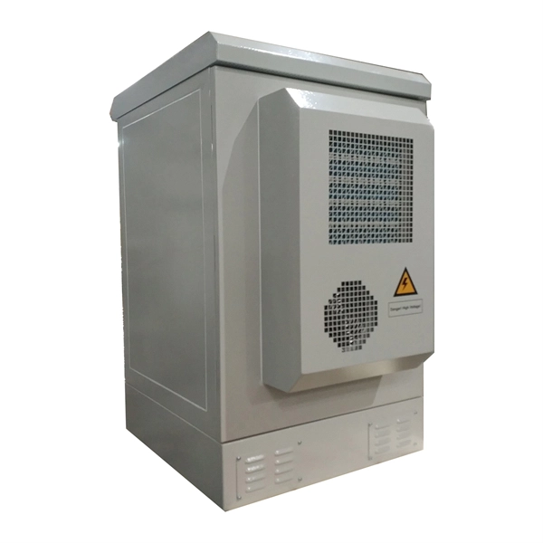
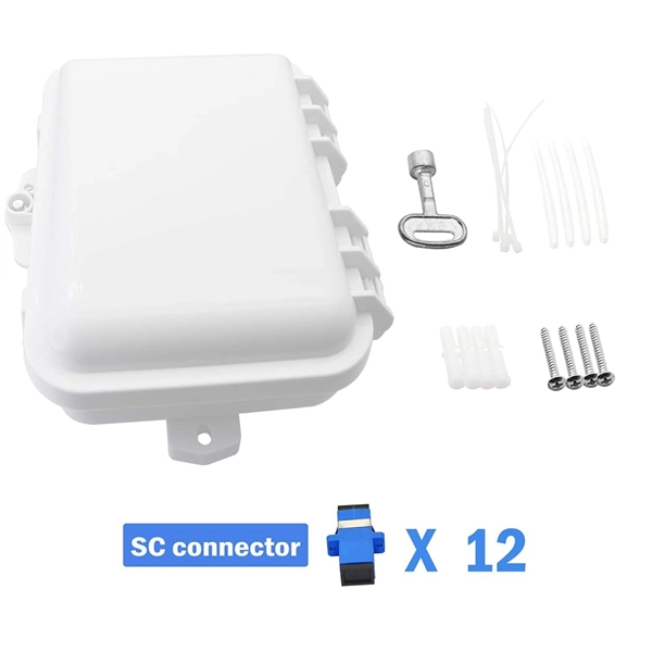
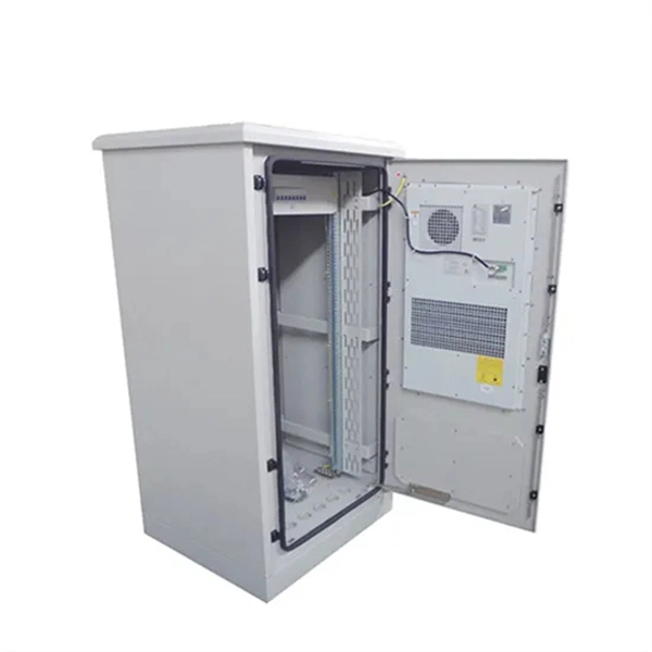
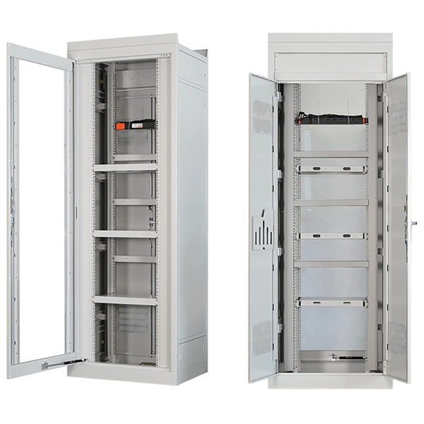
Spacing of the side of the distribution box
Side clearance: There should be a minimum of 30 inches of clearance from the sides of all electrical equipment, but in no case less than the width of the equipment itself. This is referred to as the side-to-side working space. In industrial power distribution systems, cable distribution boxes (also known as power distributor boxes, distribution electrical boxes, or electrical power distribution boxes) are the core hub of power transmission, branching, and protection. Its layout directly affects the efficiency of the. NEC Article 314 establishes requirements for the installation and use of electrical boxes, conduit bodies, fittings, and handhole enclosures. NEC Article 408. Boxes distribute low currents in an area equipped with 1 to 12 RJ 45 sockets. They centralise connections to ensure flexibility and that the installation is up to date.
[PDF Version]
-

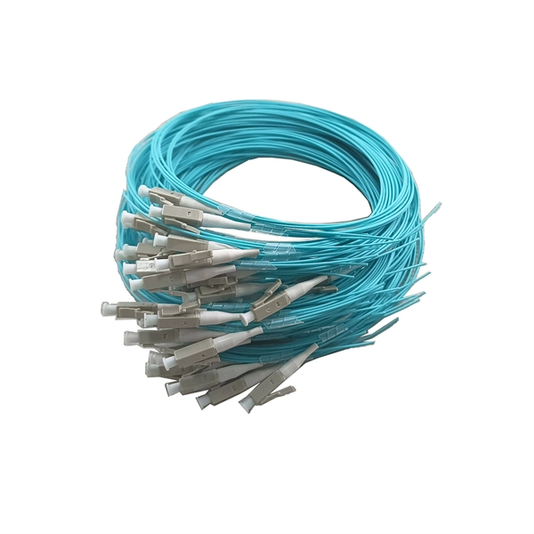
Principles and Product Design of Optical Fiber Communication
Optical Fiber Communication (OFC) revolutionizes modern telecommunications, enabling rapid data transfer across long distances with minimal signal loss. This comprehensive review explores OFC's historical evolution, core principles, components, and versatile applications. Kanade Department of Electronic-Science, P. College of ASC, Pravaranagar, India fPublished. The digital communication techniques discussed so far have led to the advancement in the study of both Optical and Satellite communications. Light acts as a carrier wave and can be modulated to carry information. Higher bandwidth (extremely high data transfer rate).