-

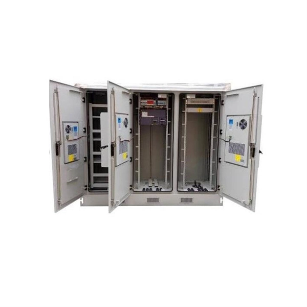
Composition of butterfly-shaped drop fiber optic cable
FTTH Butterfly Optic Cables, also known as flat drop fiber cables, feature a compact flat profile with optical fibers placed at the center and reinforced by parallel strength members on both sides. Then, the cable is completed with LSZH sheath. Also, customers can specify your required connectors. Environmental Performance. Abalone Tech's 1/2/4F Self-supporting Butterfly Drop Cable is designed for aerial and duct installations in FTTH (Fiber-to-the-Home) and telecom networks. 5 kg/km Optical Performance: Insertion loss <0.
-
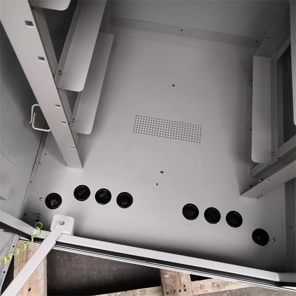
Requirements for Outdoor Drop Cable Laying
This definitive guide covers the key requirements for height, spacing, structural loads, and materials. Ensuring your cable railing is up to code in California not only tells you that it was properly installed by a competent crew, but also increases the safety of you and your family when spending time near your railing. In general, if your deck or balcony is more than 30 inches above the ground, a. Service loops are essential for maintenance. Leave about 100 feet of extra cable per 1,000 feet, and add loops at street crossings. 12) All 15- and 20-amp, 125-volt outdoor receptacles must have GFCI protection. Exception: Some snow-melting or deicing. This involves locating existing pathways, identifying potential obstacles, and measuring distances to ensure cables stay within the 100-meter limit for optimal performance. Installation Methods Compare Direct cable is a simple solution for fiber drop cable installation.
[PDF Version]
-

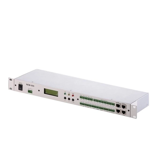
Benin Optical Cable Blowing Machine
A cable blowing machine (also known as a fiber blowing machine) is a machine designed to fit cables into telecommunication ducts and with the use of compressed air or water.
-
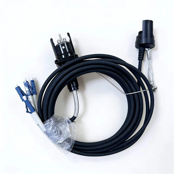
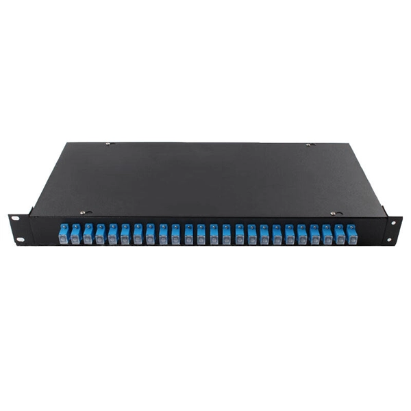
Are the pigtails terminated
Pigtails are fiber optic cables which are only terminated on one end. As networks scale to support FTTH rollouts, 5G base stations, and hyperscale data centers, the way fiber is terminated and managed at every endpoint can determine whether a project succeeds or fails. Hence the connector side can be linked to equipment and the other side melted with optical fiber cables. In order to terminate a. Executive Summary: A fiber optic pigtail is one of the most commonly specified yet least understood components in structured cabling. Get the wrong connector type, the wrong polish, or skip proper fusion splicing technique—and you're looking at elevated signal loss, increased back reflection, and a. These factory-terminated, single-connector optical fiber assemblies are the gold standard for creating clean, reliable, low-loss splices in termination boxes, splice closures, optical distribution frames (ODF), and FTTx infrastructure. Field-terminating connectors is a meticulous, high-pressure process where even a tiny mistake can force you.
[PDF Version]
-
Qatar Optical Cable Silicon Core Tube Brand
Fibre Optic Cables and Accessories have taken the networking and telecom domain in their stride and offer one of the most popular and reliable means to communicate and share data. Electra is a leadin.
-
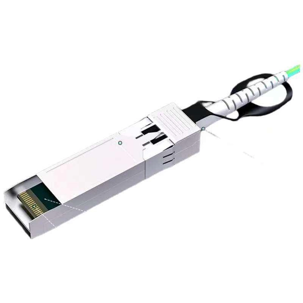
What is a fiber optic cable with a connector called
The fiber connector types, sometimes referred to as terminations, link fiber optic cables together through terminals, switches, adapters, and patch panels, by bridging the gap between their internal glass fibers that transmit the data down the length of the cable. An optical fiber connector is used to join optical fibers where a connect/disconnect capability is required. They come in various types like SC, LC, ST, and MTP, each designed for specific. The fiber connector is called a fiber optic or optical fiber connector.
-
What are the requirements for cable tray installation in factory buildings
Only approved tray-rated cables should be installed. Grounding and bonding are mandatory for metallic trays. Tray fill limits must be calculated properly. Mesh trays reduce installation time while. Cable tray systems provide a safe, organized, and flexible method for supporting insulated conductors and cables in commercial and industrial electrical installations. When properly selected and installed, cable trays simplify routing, improve accessibility, and support future expansion while. NEC Article 392 outlines the key rules for installing and maintaining industrial cable tray systems. These systems, made from metal or plastic, are open structures designed to support electrical conductors, ensuring proper organization and safety. 305(a)(3), or comparable standards promulgated by States operating OSHA-approved State plans. In addition, this document contains several references to provisions of the National Electric Code. The primary rulebook used in the safe use of cable trays is NEC Article 392.
[PDF Version]
-
Calculation of Angle Iron for Cable Trays
Enter the applied point load or uniform load. Choose whether to include self weight. Press calculate and review stress, deflection, and capacity. Calculate horizontal, vertical, or compound cable tray offsets based on bend angle, offset distance, and available installation space. Measure this distance along the straight tray. Hubbell Take Off Support provides the contractor, engineer, end user a completed BOM, including all related products, counts, symbol legends and information required to price a project. Don't spend the many hours required to do counts and create BOMs for projects, rely on Hubbell's take off. Cable tray (or cable ladder) systems are a popular alternative to electrical conduit systems, as they have an outstanding record for dependable service, design flexibility and cost savings in commercial and industrial applications. A properly designed and installed cable tray system will provide. Stop Costly Cable Tray Installation Errors Now: Avoiding Mistakes in Instrumentation Cable Tray Installation: A Guide for EPC Projects Cable tray sizing in real EPC projects is not limited to simple area calculation.
[PDF Version]
-
Fiber optic cable splice cannot be pulled out
This is often due to issues with connectors, splices, or faulty equipment. Use an OTDR to identify points of high return loss or reflection events along the link. Check the fiber's end-faces for imperfections and re-polish. A single imperfect splice can disrupt connectivity for businesses, schools, and homes, causing slow speeds, intermittent outages, and costly downtime. Whether it's from misalignment, dust contamination, environmental stress, or poor splice protection, these problems can quickly escalate if not. Successful splicing or termination relies on first being able to expose the fibers completely and safely. If the installer cannot do this, splicing or termination is irrelevant. This wikiHow article will teach you how to splice a cut fiber optic cable back together with a fiber optic stripper and cutter and a fiber optic crimper.
[PDF Version]
-
How to install the cable tray beam bend
The fittings can fastened to the cable tray rail either with double clamps of type DOP A2 or with truss-head bolts of type FRS and combination nuts. The exceptions to this are vertical bends, adjustable bend elements and fittings with a side height of 35 mm. These fittings can only be screwed on. Beam bracket PK1 is attached to the lower flange of an I beam. These guidelines are not intended to cover all details or variations in cable ladder and cable tray. en completely installed, without damage either to conductors or structural system use maintain spacing or to keep cables in place when the tray is ect the minimum bend ra-dius for cables as they exit the bottom of the cable tray. A rung spacing of 6 to 9 inches (150 to 230 mm) is preferable when. Hubbell's NEXTFRAME® Ladder Tray is the effective and widely used cable runway that supports and delivers bundles of cable between cabinets, racks, and closets, along walls, and suspended from ceilings. Cable ladder systems and cable tray systems shall be manufactured in accordance with BS EN 61537, channel support.
[PDF Version]