-
Distance between primary and secondary power distribution boxes
A minimum of 24 inches of cover for secondary (0 − 750 V) electric service, or 30 inches minimum cover for primary (over 750 V) is required for electric trench only. Cover is the distance from the outer surface of an underground facility to the top of the final grade. Primary distribution systems consist of feeders that deliver power from distribution substations to distribution transformers. At this. nt, and/or other requirements. ” Strict adherence to ons for manholes are critical. At a. This document is published to provide specifications, information, and guidance to assist developers in planning for and obtaining proper and prompt electric facilities to serve underground developments in the FirstEnergy Service territory. The requirements detailed in this document address conduit.
-
Incident Power in Fiber Optic Communication
The incident optical power is used to suppress nonlinear effects and ensure transmission quality. In the following figure, optical power at point C is the incident optical power. Why Do We Need Incident Optical Power? The transmission performance of a WDM system is affected by the. This AE Note explains the differences between Optical Return Loss (ORL) and Back Reflectance in fiber optic systems. Even minor deviations—whether too high, too low, or unstable—can impact signal integrity, trigger service alarms, or interrupt traffic on DWDM, OTN, or long-haul optical line systems.
-
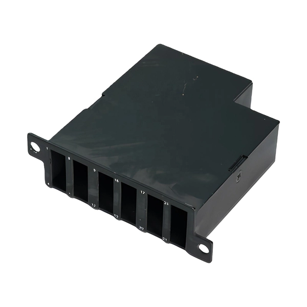
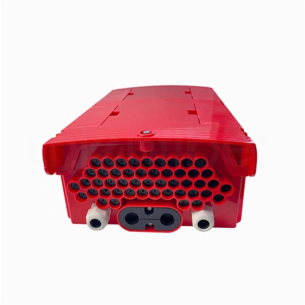
How are 36 cores of power optical fiber cable divided
Multi-core optical fiber is a breakthrough in optical networking that packs multiple cores into one fiber, enabling tremendous capacity gains via spatial division multiplexing. By carrying parallel channels in a single strand, MCF allows operators to multiply bandwidth without. These optical signals are transmitted (Tx) and received (Rx) at deliberate power levels expressed and measured in milliwatts (mW), an absolute optical power level. Absolute levels may also be represented as a relative optical power level, known decibel milliwatt or dBm. Its primary function is to split the optical signal of one input optical fiber into multiple optical signals and transmit them to. MTP/MPO cables are a class of high-density multi-core fiber optic connectivity solutions widely used in data centers and telecom networks, which are designed to achieve fast connection of multi-core fiber optics through a single interface. In contrast to conventional single-core fibers (one core on the fiber axis), MCF can have two or more.
[PDF Version]
-
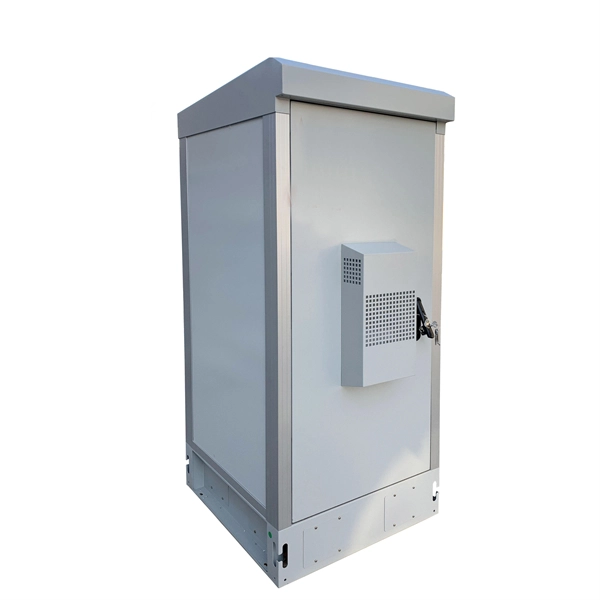
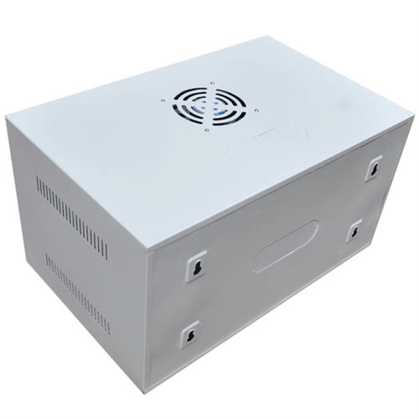
Integrated AC Power Supply System
The images below show a design example involving an isolated power supply. In this supply, we actually have two levels of isolation applied between the input and output: 1. Initially at the AC input 2. Betwee.
-
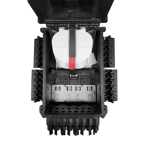
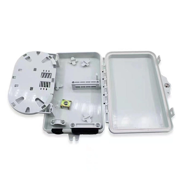
How to disconnect the power when installing a distribution box
To handle this safely, technicians must follow a strict lockout-tagout (LOTO) procedure. This ensures that no accidental reconnection occurs while the wires are being adjusted or inspected within the housing. Identify all power sources feeding the specific distribution blocks. The service disconnect rules, primarily outlined in NEC Article 230, Part VI, are fundamental to electrical safety, providing the means to de-energize an entire building from its power source. For a journeyman electrician or master electrician, a deep understanding of these regulations is. Before installation, it's important to know what makes up a distribution box. It has three categories: residential, commercial and industrial electrical distribution boxes, all of which play important roles in their respective electrical. Always shut off the power to an outlet before working on it—and then test with an electrical tester to be sure there's no voltage present. It is usually equipped with circuit breakers, fuses, terminal connectors, and other components.
[PDF Version]
-
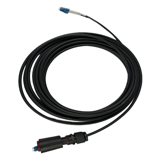
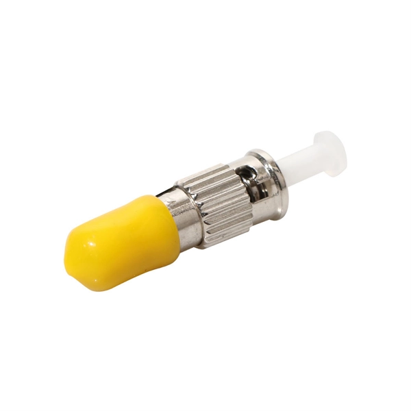
How to pull up a power fiber optic cable
Fiber optic cables should always be pulled by the strengthened yarn fibers inside the outer jacket. This article explores recommendations for pulling and installing fiber optic cable. Most fiber optic cables boast a pull strength of 100 – 200. Fiber optic cable is surprisingly strong, durable and pliable; however, several best practices should be followed to ensure a successful cable installation. Most fiber damage does not come from normal operation after the system is live. More than half of cable problems happen because of wrong pulling. In 2025, new tools like hydraulic blowers, smart monitors, and better grips help you lower risks, save money, and keep the. A duct is available from point A to point B, a pull tape is blown in, a fiber optic cable is attached to it and the cable is pulled through the duct.
-
Can fiber optic cables be run alongside 35kV power cables
General Consideration: It is generally not recommended to run fiber optic cables in the same conduit as electrical power cables. This is due to several potential risks and complications that can arise from such an arrangement. When a communications cable runs parallel and in close proximity to a power cable, these magnetic fields induce unwanted currents—a phenomenon known as inductive coupling—into the sensitive data conductors. This induced noise can. TECHNICAL GUIDELINE July 30, 2020 TG030 Rev. Electrical Interference: Electrical cables can produce electromagnetic. Maintaining proper separation between power, data, and limited energy cabling is foundational to system performance, safety, and code compliance. Other than that you haven't provided much information, given. Laying network cables parallel to electrical cables is often necessary due to space constraints but comes with its own set of challenges, primarily due to electromagnetic interference (EMI).
[PDF Version]
-
Light collection power of the second-stage beam splitter
It is currently used in modern three-CCD cameras. An optically similar system is used in reverse as a beam-combiner in three- LCD projectors, in which light from three separate monochrome LCD displays is combined into a single full-color image for projection.OverviewA beam splitter or beamsplitter is an that splits a beam of into a transmitted and a reflected beam. It is a crucial part of many optical experimental and measurement systems, such as In its most common form, a cube, a beam splitter is made from two triangular glass which are glued together at their base using polyester,, or urethane-based adhesives. (Before these synthetic,. Beam splitters are sometimes used to recombine beams of light, as in a. In this case there are two incoming beams, and potentially two outgoing beams. But the amplitudes.