-
Complete Guide to Cutting Inner Bends of Cable Trays
This guide explains how to make 90° bends, vertical bends, tees, and offsets in wire mesh cable trays safely and professionally. Horizontal 90° Bend (Flat Bend) 2. Cross Bend (4-Way. OTHER THAN 90 ̊ JUNCTIONS Use this guide to learn the most effective installation practices when installing Cablofil tray. Each example of bends and tee's clearly illustrate proper tray cutting combined with recommended usage of Cablofil accessories. Oglaend System manufacture and deliver Multidiscipline modular bolted support systems, cable trays, cable ladders and accessories for complete installation and containment of Instrument, Electrical, Telecom, HVAC and Piping. Hubbell Wiring Device-Kellems and Hubbell Premise Wiring are divisions of Hubbell Incorporated, a U. headquartered manufacturer with over 130 years of supplying solutions for the electrical and data markets.
[PDF Version]
-
How much splitter loss is used to calculate optical power
Insertion loss tells you how much weaker the signal becomes after passing through the splitter. Let's say you have a laser output at 0 dBm (which is 1 milliwatt of optical power). Factors influencing splitter loss include splitter. Instantly compute insertion loss, power at each subscriber port, and fade margin for PLC and FBT splitters — including dual cascade configurations. Covers GPON (1490 nm / 1310 nm), EPON, and RF video overlay (1550 nm). Add connector and splice quantities with realistic planning losses. Enable power budget to estimate received power and margin. Splitters are essential when you want one fiber line from a central office (like an ISP's headend or data center) to serve multiple homes or businesses.
-
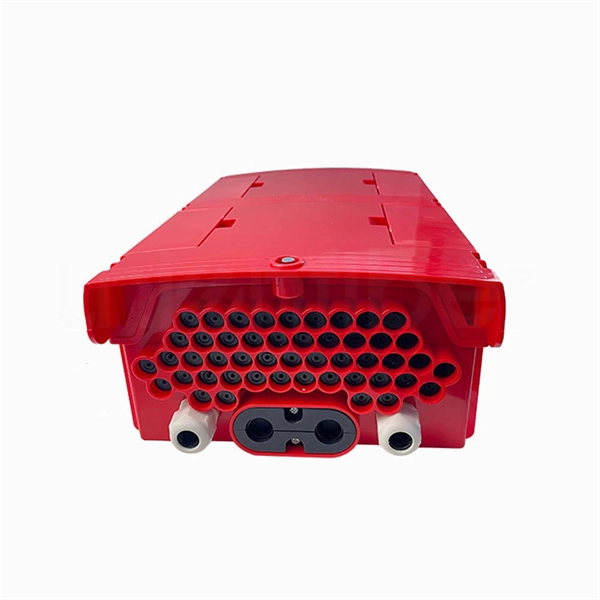
How to disconnect the power when installing a distribution box
To handle this safely, technicians must follow a strict lockout-tagout (LOTO) procedure. This ensures that no accidental reconnection occurs while the wires are being adjusted or inspected within the housing. Identify all power sources feeding the specific distribution blocks. The service disconnect rules, primarily outlined in NEC Article 230, Part VI, are fundamental to electrical safety, providing the means to de-energize an entire building from its power source. For a journeyman electrician or master electrician, a deep understanding of these regulations is. Before installation, it's important to know what makes up a distribution box. It has three categories: residential, commercial and industrial electrical distribution boxes, all of which play important roles in their respective electrical. Always shut off the power to an outlet before working on it—and then test with an electrical tester to be sure there's no voltage present. It is usually equipped with circuit breakers, fuses, terminal connectors, and other components.
[PDF Version]
-
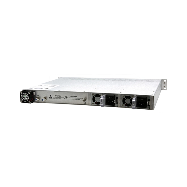
How about power communication optical cables
Power over Fiber (PoF) involves transmitting electrical power using optical fibers. CommScope solves these challenges with a complete range of powered fiber solutions designed for just the kind of high-demand powered devices that power smart networks in healthcare, hospitality, education, transportation and government environments, among others. That conversion can be done with a photovoltaic cell. A: OPGW (Optical Ground Wire) is a power transmission cable featuring dual functions on overhead lines. The power line protects (in lightning strikes) and the fiber for high-speed data communications. Widely used in overhead transmission lines, OPGW plays a crucial role in modern smart grids, telecom integration, and utility infrastructure. Utilities build fiber optic. This composite cable combines the distance and bandwidth capabilities of singlemode fiber with the power-carrying capability of 14-AWG copper conductors. by Jeanna Deese and Chris Rivas Power over Ethernet—it may be an old concept, but new applications continue to be identified that are redefining.
[PDF Version]
-
How to determine light attenuation of red light using an optical power meter
Optical attenuation compares input and output power on a logarithmic scale. When powers are in linear units, the loss in decibels is: Attenuation (dB) = 10 × log10 (Pin / Pout) If the link length L is provided, the attenuation coefficient is: Coefficient (dB/km) =. Analyze optical power drop across fibers and links. Switch units, lengths, and calculation modes easily. Needed when attenuation is an. Optical power, required for measuring source power, receiver power and, when used with a test source, loss or attenuation, is the most important parameter and is required for almost every fiber optic test. Backscatter and wavelength measurements are the next most important and bandwidth or. Optical power meters are a key element in the optimization and maintenance of such optical networks and of their components. But, for designers, just starting to work in the fiber-optic design space, measuring attenuation can seem like a monumental task.
[PDF Version]
-
How to use a red light power meter
Lets say you are a light therapy enthusiast that wants to take your own proper measurements. Or you bought a red light therapy product and want to verify it meets outputs the intensity that it claimed. Then.
-
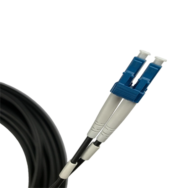
How to pull up a power fiber optic cable
Fiber optic cables should always be pulled by the strengthened yarn fibers inside the outer jacket. This article explores recommendations for pulling and installing fiber optic cable. Most fiber optic cables boast a pull strength of 100 – 200. Fiber optic cable is surprisingly strong, durable and pliable; however, several best practices should be followed to ensure a successful cable installation. Most fiber damage does not come from normal operation after the system is live. More than half of cable problems happen because of wrong pulling. In 2025, new tools like hydraulic blowers, smart monitors, and better grips help you lower risks, save money, and keep the. A duct is available from point A to point B, a pull tape is blown in, a fiber optic cable is attached to it and the cable is pulled through the duct.
-
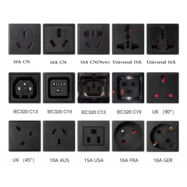
How to select the power cord for the distribution box
Some distribution boxes have a longer cord than others. If it's too short, you may not be able to connect the distribution box. Covers wiring, placement, standards, and expert tips for a compliant setup. In modern electrical systems, cable distribution boxes (also known as electrical distribution boxes or distribution boxes) play a crucial role as the key hub for managing, distributing, and protecting circuits. Key Takeaways: Begin cable and conductor. With designations such as NM and UF, building cable brings power to wall outlets and outlet boxes Make connections in low-voltage vehicle wiring systems Connect servocontrollers and servomotors in automated equipment and on assembly lines With designations such as THHN or THWN, building wire brings. Hey, in this article we are going to see the Single Phase Distribution Box Wiring Diagram and Connection Procedure. And all the switching and protective devices are installed in the.
[PDF Version]