-
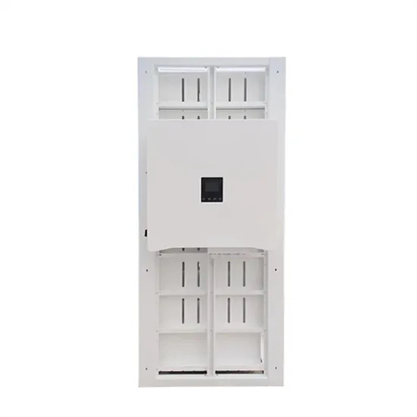
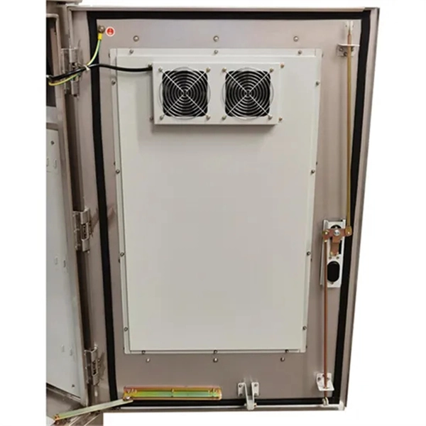
The Role of UPS Power Supplies in Industrial Control Systems
The Role of Industrial Grade UPS Systems Industrial grade UPS systems are designed to provide a continuous and stable power supply to manufacturing equipment, ensuring that operations can continue uninterrupted even in the event of a power outage or electrical disturbance. A control panel contains specific control devices in an automated system such as PLCs, HMI's, motion drives, safety sensors, network switches, among many others. Even with decentralized systems, the power source for the embedded control hardware comes from the main panel. Unlike standard UPS systems, industrial-grade units are built to. Drawing from Delta Wye Electric's 45+ years of experience installing and maintaining industrial UPS systems across manufacturing, pharmaceuticals, and critical infrastructure, this guide provides the technical insights facility managers and engineers need to make informed decisions. For facilities seeking a proven solution, the GTL33 Low Frequency Online UPS series (10–600kVA).
[PDF Version]
-

Normal transmit and receive power of optical module
Transmit power is typically good when it is in the 6 dB range between -1 and -7 dBm. This guide provides average transmit and receive power ranges for transceiver modules. The TX (transmit) and RX (receive) power levels significantly affect everything from signal strength to transmission distances and the overall optical power. For network engineers working with fiber optics (SFP, SFP+, QSFP), understanding TX (Transmit) and RX (Receive) signal strength is critical.
-
Function of DC Power Supply Remote Module
The MagnaDC power supply remote sense implements Smart Sense Detection, which shuts down and protects the product in the event that sense leads are disconnected while live or when the user leaves leads disconnected on start. Remote sense moves the feedback point external to the. The remote sense and trim functions of many DC DC converters seem easy enough to apply but, for optimum performance and minimum noise, some easily followed guidelines can prevent surprises in the customer's system. Remote sensing allows the customer to overcome voltage drops in the power lines by. Programmable DC power supplies are essential tools that can source power to a connected device. This article discusses – oscillations.
-

Optical module test power not adjusted too low
What does it mean if the transmitted power is too low? Low transmitted power can mean the connectors are dirty. Clean the connectors, check the module, and look at the fiber. If it still does not. Stable optical power is the foundation of every high-capacity optical transport system. Even minor deviations—whether too high, too low, or unstable—can impact signal integrity, trigger service alarms, or interrupt traffic on DWDM, OTN, or long-haul optical line systems. Because optical networks. The article Digital Diagnostic Function (DDM) For Optical Modules describes that DDM function can be used for real-time monitoring and fault location of the module's working status, in which the optical module's transmitting optical power and receiving optical power are the key parameters for. To test transmitted power in sfp optical modules, you use an optical power meter to get exact results. Many sfp modules also have DOM/DDM, which lets you see digital diagnostic monitoring data on network equipment. Built into modern SFP/SFP+/ SFP28 /QSFP family modules and standardized by SFF-8472, DDM/DOM exposes real-time values for the module's temperature, supply.
[PDF Version]
-
Optical Module Power Sensitivity
Receiver sensitivity is the lowest optical power level at which an optical receiver can successfully decode data with acceptable bit error rates (BER). It's a core parameter in optical transceiver specifications, indicating the module's capability to detect weak incoming signals. The transmitted optical power is related to the proportion of "1"s in the transmitted data signal; the more "1"s, the. Transmitter power characterizes the average optical power output from the laser under rated conditions, while receiver sensitivity indicates the minimum detectable power required to maintain a low bit error rate. An understanding of these concepts is pivotal to establishing an effective and efficient optical network.
-
Power of optical communication module
Modern optical module designs often require: Reduced power consumption to control and limit module temperature rise. Dynamic and precise control of laser diodes to regulate output power. Find products and reference. As an essential component of optical fiber communication, optical modules are optoelectronic devices that facilitate the conversion between optical and electrical signals during the transmission process. Operating at the physical layer of the OSI model, optical modules are core devices in optical. Optical modules — the foundation of optical communication networks — face the design challenges of requiring higher density power, integration, and improved efficiency conversion. Whether you are creating a 100-Gbps or 400-Gbps, small form-factor pluggable (SFP) module, SFP+ transceiver, XFP module, CFP, X2/XENPAK module.
-
The higher the optical power of the optical module the better
The optical power budget represents the maximum allowable signal loss in a fiber-optic link. It is calculated by subtracting the RX sensitivity from the TX power. The transmitted optical power of the optical module is an important parameter that affect the transmission distance of the optical module. The stronger the. In the world of enterprise and data center networking, Small Form-factor Pluggable (SFP) modules are the quiet workhorses that connect routers, switches, and optical fiber links.
-
Increase the light output power of the optical module
An optical amplifier is a device which receives some input signal light and generates an output signal with higher optical power. Typically, inputs and outputs are laser beams (very rarely other types of light beams), either propagating as Gaussian beams in free space or in a fiber. At the receiver end, the optical signals are reconverted into electrical. In this guide, we will explain what optical signal strength is, how to check it on Cisco IOS using the command line, and how to troubleshoot common light level issues. Assume the. This application note gives a short introduction to optical modules and the need of an optimized power tree in them and then concentrates on the use cases and benefits of four-switch and inverting buck-boost converters inside optical modules.
-
Huawei optical module power failure alarm
The optical module is faulty or not securely installed. If the transmit optical power is abnormal, replace. Run the display interface transceiver command to check whether any alarm information has been generated for the optical module. Alarm information: LOS Alarm RX LOL Warning information: If the LOS alarm is displayed, the local optical interface does not receive signals from the remote. The transmit power of the AP's optical module fell below the lower threshold. Indicates the MIB object ID of the alarm. During use, reading optical module information helps understand its real-time operating status, enabling faster troubleshooting of link abnormalities.
-
Light collection power of the second-stage beam splitter
It is currently used in modern three-CCD cameras. An optically similar system is used in reverse as a beam-combiner in three- LCD projectors, in which light from three separate monochrome LCD displays is combined into a single full-color image for projection.OverviewA beam splitter or beamsplitter is an that splits a beam of into a transmitted and a reflected beam. It is a crucial part of many optical experimental and measurement systems, such as In its most common form, a cube, a beam splitter is made from two triangular glass which are glued together at their base using polyester,, or urethane-based adhesives. (Before these synthetic,. Beam splitters are sometimes used to recombine beams of light, as in a. In this case there are two incoming beams, and potentially two outgoing beams. But the amplitudes.
-
How to use a red light power meter
Lets say you are a light therapy enthusiast that wants to take your own proper measurements. Or you bought a red light therapy product and want to verify it meets outputs the intensity that it claimed. Then.