-
How to tell the positive and negative terminals in your home s electrical panel
According to master electrician James Hornof, for DC power, the red wire is generally positive and the black wire is usually negative. The red wire is a phase 2 hot wire, and the white wire. When you're dealing with electrical wiring, it's important to know which is positive and which is negative—but how are you supposed to tell them apart? The easiest way to tell is by looking at the color, but the colors mean different things depending on what kind of power is being used. Whether you are replacing a fixture, troubleshooting a circuit, or simply trying to understand your home's electrical. The positive wire carries the current from the power source to the load, while the negative wire returns the current back to the source. To identify the positive wire, look for markings such as a plus sign (+), the color red, or words like “positive” or “pos” on the wire insulation.
[PDF Version]
-
How to install a long fiber optic panel
The process involves a combination of national infrastructure, local engineering, and property-level setup. In this guide, we'll break down the fiber installation process from start to finish and explain key components such as fiber cabinets, flower pods, ducting, and ONT setup. Fiber transmits data using light signals through glass strands, delivering faster speeds and lower latency than cable or DSL connections that rely on. Mastering fiber optic installation is key. Discover the. How long does it take for fiber internet to be installed if you are a new customer? For new AT&T Fiber customers, installation will require a technician to come to your home. You can expect the visit to take about four to six hours. Follow our video and upgrade your cabling system today! The FHD series offers diverse fiber patch panels, providing faster, easier, and more efficient.
[PDF Version]
-

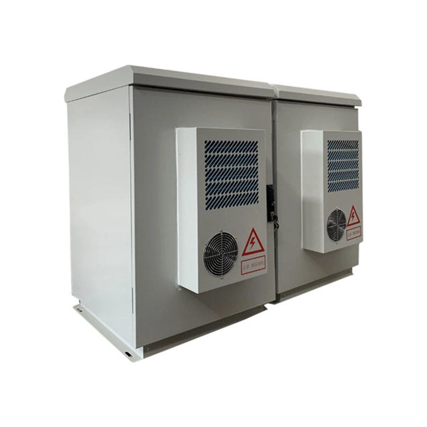
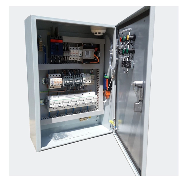
Check the load of the distribution box
Check the electrical load and ensure that the sensors do not exceed the 10 Amp maximum. Check the tightness of electrical connections along the. Professional electrical panel schedule tool for creating detailed load distributions, calculating circuit loads, balancing phases, and ensuring NEC compliance for electrical distribution panels. Check your panel often. Have a professional check it every 3 to 5 years to keep things safe. Do not make mistakes like adding breaker ratings wrong, using the wrong wire size, or missing hidden loads. Supporting 120/240V single-phase AC, this indoor circuit breaker panel provides a compact and organized solution for managing branch. The best distribution system is one that will, cost-effectively and safely, supply adequate electric service to both present and future probable loads—this section is intended to aid in selecting, designing and installing such a system.
[PDF Version]
-
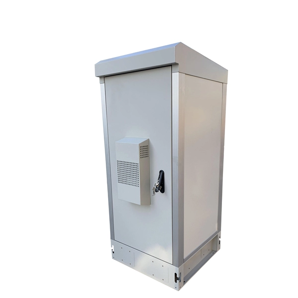
How to select circuits on the distribution box panel
Use electrical diagrams to see where circuits go. Make sure the breaker matches what it protects. This stops fires and helps everything work right. What size distribution box do you need for a house? How do you know which circuit breaker to use? Can you add more breakers later? Why do you need GFCI or AFCI breakers? Choosing the right size and setup for your distribution box keeps your electrical system safe and working well. You lower the. This guide provides information on how to select the appropriate Distribution Box for Electric project. Whether you're upgrading your home's electrical service, designing a commercial facility, or managing an industrial power system, selecting and sizing the right. The distribution box (DB box) plays a key role in safely and efficiently distributing electrical power.
-

How many A s should I choose for the main control panel in my home s electrical distribution box
The right panel size depends on factors like your home's square footage, appliances, and future plans. For smaller homes, a 100-amp panel may suffice. Checking the amperage of your. One of the first things you should do on the path to electrifying everything (or anything!) in your home is to check the size of your home's electrical panel. This will help you determine if you can add new loads to your existing panel without requiring a panel or service upgrade. At Root Electric, we've been helping Northern Virginia homeowners with electrical panel upgrades and replacements since 1986. Whether you're. This is because accurately determining the size of main panels and load center ensures they can safely and efficiently handle the current load, as well as any potential future loads. Load centers and distribution boards should be sized in compliance with NEC, IEC, or other relevant regional codes.
[PDF Version]
-
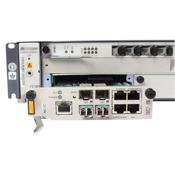
How to install a 24-port network patch panel
This video shows how to punch down 24 port patch panel (cat6 patch panel wiring) and also showing Live 15 U network rack mounted on wall equipped with d'link patch panel 24 port, network cable (cat 6 cable) manager and 24 port d'link network switch. So, you purchased all of your shielded solid copper Ethernet cable, shielded keystone jacks, termination tools, and are ready to get your installation started! Finally, a wired network to install your outdoor security cameras rather than relying upon potentially unreliable Wi-Fi. Did you. A patch panel is an essential component in networking, serving as a central point for connecting various network cables. Effective cable management is crucial for maintaining an o. Even as Wi-Fi 6E and Wi-Fi 7 push uplink bandwidth to 5G/10G and. F. This installation guide focuses on what a patch panel does, patch panel installation basics, and how to connect patch panel to switch while keeping cabling. Ubiquiti, Ubiquiti Networks, and the Ubiquiti U logo are trademarks or registered trademarks of Ubiquiti Inc. in the United States and in other countries. All other trademarks are the property of their respective owners.
[PDF Version]
-
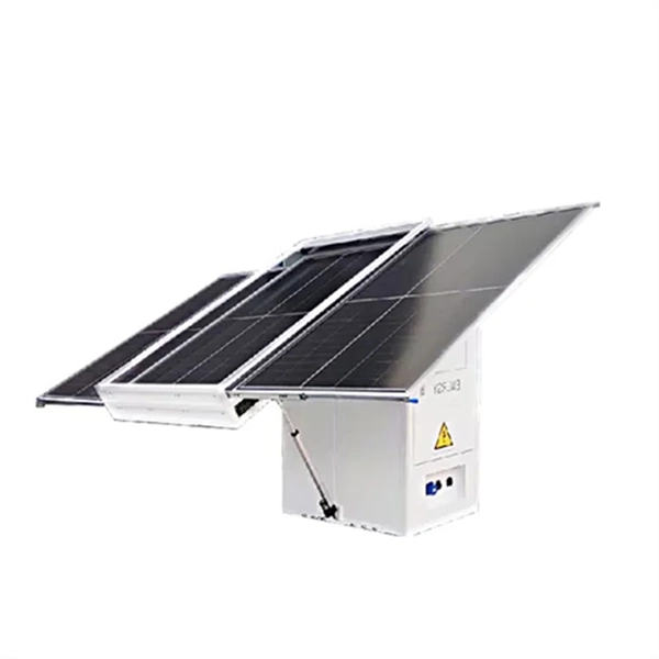
What are the smart photovoltaic panel modules
A smart solar module is an advanced solar panel that is equipped with an integrated DC power optimizer. Add a shadow from a chimney, a second roof plane, or a. The smart solar modules connect to the IoT (Internet of Things), allowing you to monitor and control your energy usage online via a smartphone or tablet. Also, they come with. Integrated with our Power Optimizers for maximum energy production, enabling faster installation, simplified logistics, easier servicing, and advanced safety mechanism. We've combined our industry leading DC optimization technology with enhanced module performance for greater module output. One particular component type—the smart module—has been increasing in popularity because of its benefits compared to traditional modules.
-
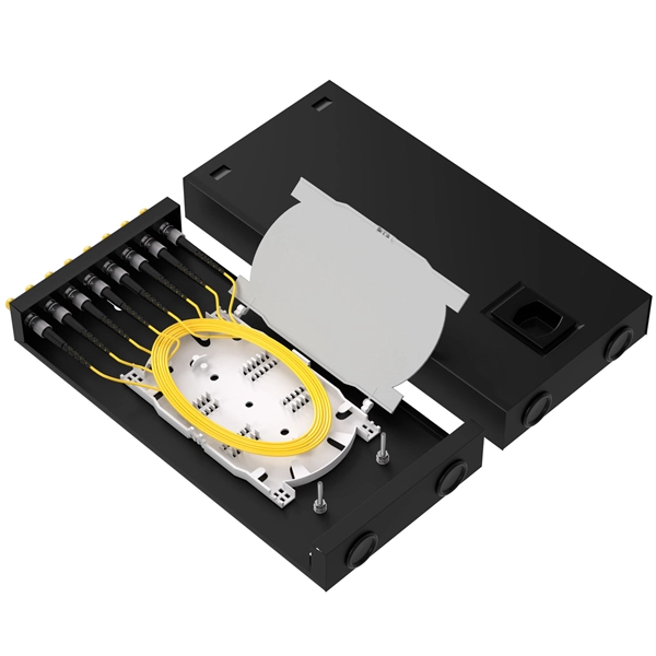
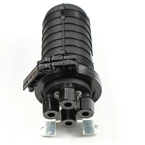
ODF patch panel without pigtail
The ODF panel is mainly used for interconnection between units within sites and fits in 19” standard racks also with metric mounting pattern. The ODF supports SC-cut out type of adaptors. The unit is designed for installation of pre-terminated cables. Whether you are searching for a high-density rack mount fiber optic patch panel for a data center or a compact wall mount fiber optic patch panel for a remote building entry point, our solutions ensure organized cabling and easy maintenance. These panels protect delicate fiber splices from damage. ODFs are robust enclosures (often wall-mounted or free-standing racks) designed to protect delicate splices and terminations from dust, physical damage, and excessive bending. In an era where data speeds and network reliability are non-negotiable, the patch. This 2026 expert guide explains the functions, placement, structure, and application scenarios of ODFs and fiber patch panels-and includes a deep engineering FAQ that resolves real-world deployment challenges.
[PDF Version]
-
Fiber Optic Cable Tension Load Test Standard
This Applications Engineering Note (AEN 135) explains and recommends standard measurement methods for characterizing optical fiber system performance. FOA procedures, such as OFSTP-7 (single-mode) and OFSTP-14 (multimode), align with TIA and IEC standards. They describe how to set a '0 dB' reference, control mode power distribution, and use proper wavelengths. These procedures ensure you get consistent, repeatable results that meet international. d suppliers of electrical construction services. We're here to support your fiber network needs.
-
WDM Fiber Optic Communication System Design
This lesson demonstrates the basic features of a typical WDM optical communication system and shows the basic design steps with OptiSystem. The performance of the system will be shown and compared. In fiber-optic communications, wavelength-division multiplexing (WDM) is a technology which multiplexes a number of optical carrier signals onto a single optical fiber by using different wavelengths (i. Single mode fiber is favored over Multimode fiber for long-distance communication. Firstly, the WDM optical. While fiberoptic technology resulted in a significant increase in a network's "bandwidth," or the amount of information that the network could send, tbe creation of the Internet resulted in an even greater demand for bandwidth. As demand for network capacity increased, service providers exhausted.
-

Principles and Product Design of Optical Fiber Communication
Optical Fiber Communication (OFC) revolutionizes modern telecommunications, enabling rapid data transfer across long distances with minimal signal loss. This comprehensive review explores OFC's historical evolution, core principles, components, and versatile applications. Kanade Department of Electronic-Science, P. College of ASC, Pravaranagar, India fPublished. The digital communication techniques discussed so far have led to the advancement in the study of both Optical and Satellite communications. Light acts as a carrier wave and can be modulated to carry information. Higher bandwidth (extremely high data transfer rate).
-
Requirements for Relay Protection Design
The IEEE standard for protection relays refers to a collection of guidelines developed by the Institute of Electrical and Electronics Engineers. This document provides recommendations, background and philosophy on relay protection that is not available in M07. They are intended to quickly identify a fault and isolate it so the balance of the system continue to run under normal conditions. For professionals working in utilities, industries, or renewable energy systems, understanding these standards is not optional—it is essential. This handbook covers the code of practice in protection circuitry including standard lead and device numbers, mode of connections at terminal strips, colour codes in multicore cables, dos and donts in execution.