-
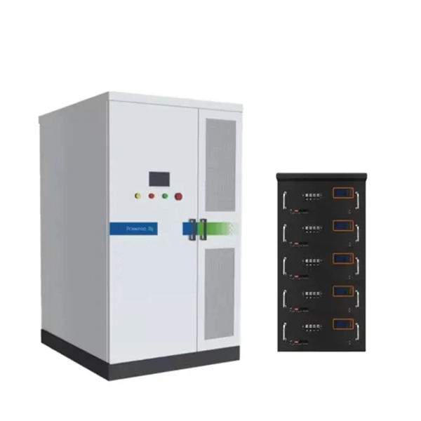
Egypt Solution ONU Optical Network Unit PAM4
A physical-layer network coding (PNC) based inter-ONU-communication (IOC) scheme is proposed for next generation high-speed PONs which apply four-level pulse amplitude modulation (PAM4). A 25 Gb/s f.
-

Syrian PAM4 optical transmitter
The system in this example contains the following elements: 1. 2 Pseudo-random Bit Stream (PRBS) block 2. 2 NRZ Pulse Generator (NRZ) 3. 1 CW Laser (CWL) 4. 3 1x2 Fork (FORK) 5. 2 Electrical Not Gate (N.
-
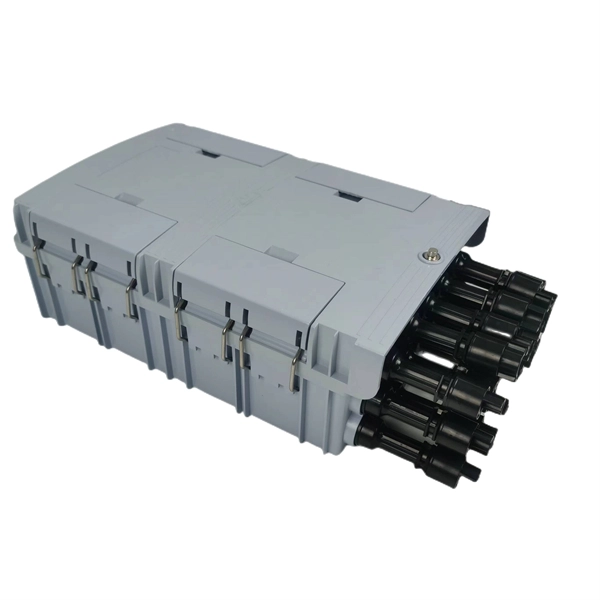
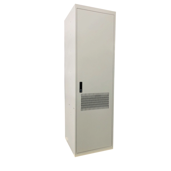
144 Optical cable connected to optical distribution box
This frame is ideal for indoor fiber optic cables connection storage, distribution and management. ●Features: • Modular design with splicing and distribution function • Standard size, light weight and reasonable structure • Compact design for space saving • Suitable. The 144-core ODF optical fiber distribution frame can solve this problem perfectly for our wiring project, but we are in optical fiber wiring. 144-port fiber optic. Optical Distribution Frame (ODF) is a device used in fiber-optic telecommunications networks to connect, manage and distribute optical fibers from incoming and outgoing cables. The cabinet is with excellent performance, safe and reliable, flexible scheduling, and is. A Fiber Optic Patch Panels includes up to 12 duplex SC connectors, as well as an integrated IDC shroud with strain reliefs that are compatible with standard small form factor (SFP) transceivers. Users can select unit or ring flange amount according to their practical needs. The frame design is based on a 4U rack unit height.
[PDF Version]
-
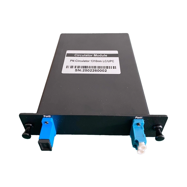
Increase the light output power of the optical module
An optical amplifier is a device which receives some input signal light and generates an output signal with higher optical power. Typically, inputs and outputs are laser beams (very rarely other types of light beams), either propagating as Gaussian beams in free space or in a fiber. At the receiver end, the optical signals are reconverted into electrical. In this guide, we will explain what optical signal strength is, how to check it on Cisco IOS using the command line, and how to troubleshoot common light level issues. Assume the. This application note gives a short introduction to optical modules and the need of an optimized power tree in them and then concentrates on the use cases and benefits of four-switch and inverting buck-boost converters inside optical modules.
-
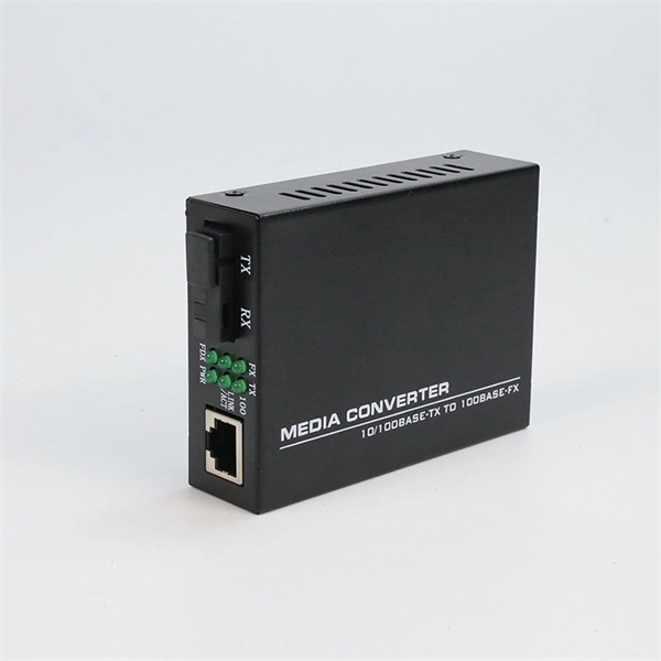
Is an optical module a chip
Optical module chips are semiconductor devices that enable high-speed data transmission in fiber optic networks. These components form the core of optical transceivers, converting electrical signals to optical signals (and vice versa) for telecommunications and data center. Optical modules and optical chips are two closely related but hierarchically distinct core concepts in optical communication systems. They differ fundamentally in functional positioning, structural composition, technical complexity, and application approach. Optical modules typically have an electrical interface on the side that connects to the inside of the system and an optical interface on the side that connects to the outside. The optical module serves as a crucial component in optical fiber communication systems, operating at the physical layer, which is the lowest layer in the OSI model. An. That is, metal medium communication represented by coaxial cables and network cables is gradually being replaced by optical fiber media.
[PDF Version]
-
24-core optical fiber cable color code
Tubes with 24 uniquely colored fibers: Fibers 1 to 12 use the standard blue through aqua color sequence. Understanding fiber‑optic color codes is essential for any technician tasked with installing, maintaining, or troubleshooting modern fiber networks. By adopting the TIA/EIA‑598C standard, you gain a universal “language” of colors that speeds identification, reduces miswiring, and enhances safety. This guide explains the latest EIA/TIA-598-D fiber color-coding standard used to identify fiber types, inner fiber sequences, and connector polish styles. This sequence is used by UMH1A1J-24, MDS1JKT-24, and the LongSpan ADSS designs when 24 fibers per tube are specified. This standard also allows fiber units to be identified by other discernible colors as agreed to by the manufacturer and the user.
-
Finding Faults in Optical Time Domain Reflectometers
An OTDR sends pulses of light down a fiber optic cable and measures the reflected signals. These reflections indicate splices, bends, breaks, and other faults. What Is an OTDR? What Is an OTDR? An OTDR is. Download free OTDR Trainer Software for PCs After you study this page, you can download a free OTDR Trainer to run on your PC. It provides an expert-curated supplier directory, buyer-focused technical background information, and structured selection criteria to support professional procurement decisions. With the help of this device, engineers and technicians can accurately assess and diagnose fibers and cables. This guide seeks to clarify the perceived complexities of OTDR. An Optical Time Domain Reflectometer (OTDR) is a precision tool used to detect faults and measure loss along fiber optic links by analyzing backscattered light from high-speed pulses.
[PDF Version]
-
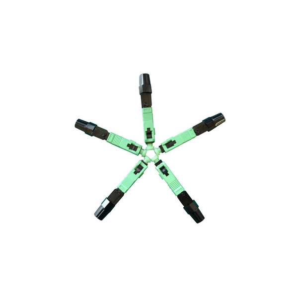
How to cut optical cables after production
Cutting fiber optic cable requires precision and the right tools to avoid damaging the delicate glass fibers that transmit data; the correct method involves scoring the outer jacket and then snapping the cable clean, ensuring a clean break for future splicing or termination. In this video, you will learn how to cut optical fiber cable step by step. This tutorial is perfect for beginners and professionals working with fiber optic cable installation and maintenance. You may also want to. 1. 1 Improper use of a respooler (Figure 1) can cause damage to a cable jacket or result in wavy fiber in tight buffered cables due to cable crossovers or excessive tensile loading. These cables are made of extremely The content is structured to help readers understand the key concepts and practical applications.
-
What is the IN port of the optical splitter
Signal Ingress: The incoming optical signal (carrying data as light pulses) enters the splitter through a single input port, typically connected to a main fiber from the network provider. Unlike active devices (which require power), splitters operate without electricity, relying solely on the physics of. Orion offers 1x2 Optical Splitters in 90:10 and 80:20 ratios. Mathematically: where IL (i) is the insertion loss at the i-th output port, P (out,i) is the optical power at the i-th. What is a PLC Splitter? A PLC (Planar Lightwave Circuit) splitter is a type of single-mode splitter that can evenly distribute the optical signal from one input fiber to multiple output fibers. This uniform distribution is critical for maintaining signal quality and transmission efficiency. Bandwidth is shared amongst customers in a PON, and the bandwidth received by a customer is not related to the power received at the optical network terminal (ONT) as long as the power is high enough so the ONT can operate. Its manufacturing process is very intuitive: two or more stripped, coated optical fibers are bundled side by side in a specific configuration and uniformly stretched in opposite.
[PDF Version]
-
The function of optical cable coiling
The coiling system must maintain balanced tension, consistent feed speed, and smooth direction transitions. The modern coiler uses a wire arrangement tool to ensure perfect layering—each loop sits exactly beside the previous one, maintaining the coil's structure. The modern fiber optic cable is the backbone of global communication networks, connecting continents through vast data highways. Today's automatic winding tools have. Fiber optic cable filling compound is not ordinary “grease” or “petroleum jelly,” but rather a semi-transparent paste-like functional material composed of base oils, thickening systems, water-blocking components, antioxidant systems, and other materials. The cable coiling and reserving device has a simple structure, offers convenient assembly and use, and can avoid accidental pull-out of a coiled and stored cable caused by. The CableCoiler 1300 is a standalone, fully synchronized high performance cable coiler for Schleuniger cut and strip machines. Often, coils are made with a.
[PDF Version]
-
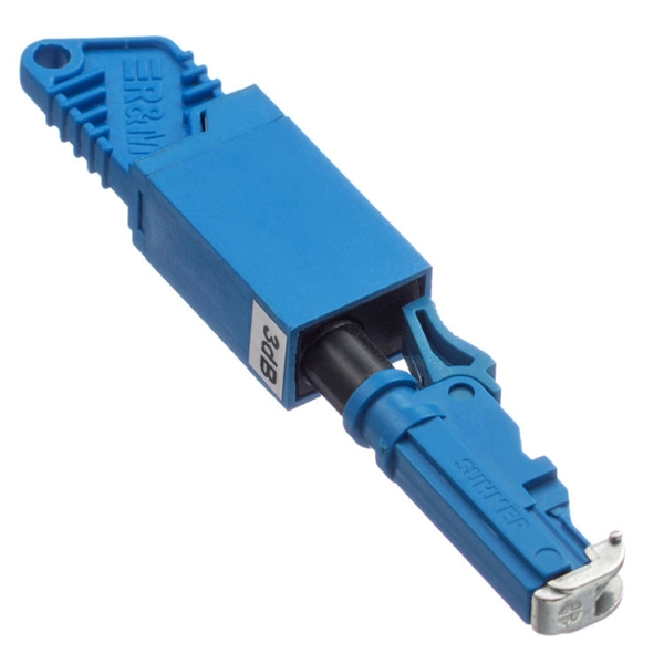
How is the serial interface of the XFP optical module
The XFP 2-wire serial interface is used for serial ID, digital diagnostics, and certain control functions. It was defined by an industry group in 2002, along with its interface to other electrical components, which is called XFI. XFP modules can be installed or replaced in an Extreme Networks switch, I/O module, or router without powering off the system. All Extreme Networks XFP modules comply with. This Juniper Networks® XFP-10G-S compatible XFP transceiver provides 10GBase-SR throughput up to 300m over multi-mode fiber (MMF) using a wavelength of 850nm via an LC connector. It can operate at temperatures between 0 and 70C. The transceiver is compliant with CPRI, eCPRI. With these features, this 10G SFP+. ID systems defined for the GBIC and SFP transceivers. 12 document apply to Beta-and Production-level units only. Physical Medium Dependent (PMD) sublayer and baseband medium, type 10GBASE-S (short wavelength serial), 10GBASE-L (long wavelength serial), and.
[PDF Version]